In this note, we are going to know about 8051 Interfacing with Stepper Motor with Program of C and Assembly Language. Welcome to Poly Notes Hub, a leading destination for engineering notes for diploma and degree engineering students.
Author Name: Arun Paul.
8051 Interfacing with Stepper Motor
ULN2003 or ULN2803 driver ICs are often used to interface stepper motors with 8051 microcontrollers. The 8051 cannot supply enough current to run the motor directly, hence a driver IC is required. Here’s a step-by-step guide.
About ULN2003 or ULN2803 driver IC
The ULN2003 is a high-voltage, high-current Darlington transistor array used to power stepper motors, relays, solenoids, and high-power LEDs. It serves as an interface between low-power microcontrollers (such as the 8051, Arduino, or PIC) and high-power loads.
Features of ULN2003 Driver IC
- It can easily drive 7 different loads.
- It has high output current like 500mA per channel.
- This driver has high voltage handling capability (Up to 50V)
- It has Built-in freewheeling diodes for inductive load protection.
- Available in 16 pin DIP & SOIC packages.
- TTL & CMOS compatible. So, it can easily interfaced with 8051 microcontrollers.

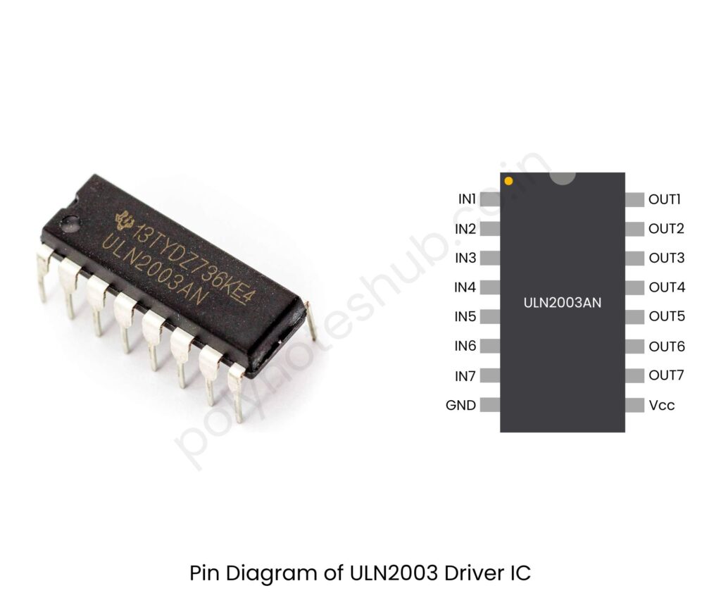
ULN2003 Driver IC Pin Configuration
| Pin No. | Name | Description |
|---|---|---|
| 1 to 7 | IN1 to IN7 | Input control pins (connected to MCU) |
| 8 | GND | Ground Terminal |
| 9 | COMMON | Common pin (connect to VCC for protection diodes) |
| 10 to 16 | OUT7 to OUT1 | Output pins (connect to motor or load) |
Components Required for 8051 Interfacing with Stepper Motor
Here are the list of components that are required to make the connection diagram of 8051 interfacing with stepper motor –
- 8051 Microcontroller (e.g., AT89C51)
- Stepper Motor (e.g., 28BYJ-48 or any unipolar/bipolar stepper motor)
- ULN2003 or ULN2803 Driver IC (for controlling the motor)
- Power Supply (5V or 12V, depending on the stepper motor)
- Connecting Wires
- Crystal Oscillator (11.0592 MHz)
- Capacitors (22pF)
- Resistors (10kΩ)
- Push Buttons (for manual control, optional)
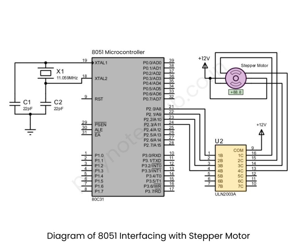
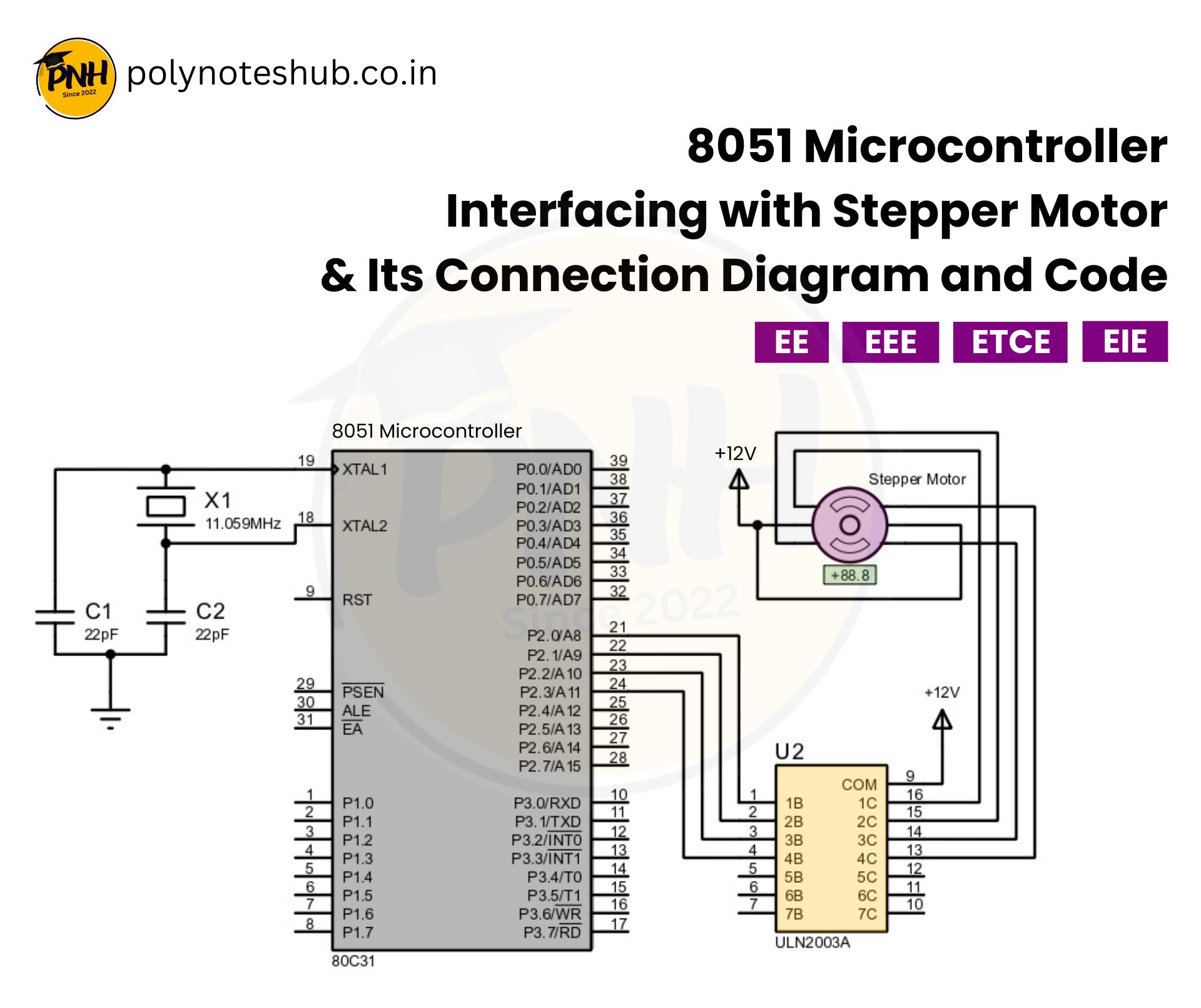
Connection Diagram of 8051 Interfacing with Stepper Motor

Stepper Motor to ULN2003/ULN2803:
- The stepper motor has 4 control wires or 2 coils.
- Connect the 4 control wires to the ULN2003/ULN2803 driver IC inputs.
- The common wire connects to Vcc (5V or 12V).
ULN2003/ULN2803 to 8051:
- The four input pins of ULN2003/ULN2803 are connected to P2.0, P2.1, P2.2, and P2.3 of the 8051.
Power Supply:
We are requires two power supply, one for 8051 microcontroller and another for the stepper motor –
- 8051 operates on 5V.
- Stepper motor requires 5V/12V depending on the type.
Stepper Motor Connections with ULN2003
| 8051 Microcontroller | ULN2003 Driver IC | Stepper Motor |
|---|---|---|
| P2.0 | IN1 | Coil 1 |
| P2.1 | IN2 | Coil 2 |
| P2.2 | IN3 | Coil 3 |
| P2.3 | IN4 | Coil 4 |
| GND | GND | – – – – |
| Vcc (5v) | Common Wire | Vcc (5V/12V) |
Stepper Motor Interfacing with 8051 Microcontroller Program
#include <reg51.h>  // Header file for 8051

#define delay_time 500  // Delay for step control

// Define stepper motor pins
sbit IN1 = P2^0;
sbit IN2 = P2^1;
sbit IN3 = P2^2;
sbit IN4 = P2^3;

// Function to create a small delay
void delay(unsigned int time) {
    unsigned int i, j;
    for(i = 0; i < time; i++)
        for(j = 0; j < 1275; j++);
}

// Function to rotate stepper motor in clockwise direction
void stepper_clockwise() {
    IN1 = 1; IN2 = 0; IN3 = 0; IN4 = 0;
    delay(delay_time);

    IN1 = 0; IN2 = 1; IN3 = 0; IN4 = 0;
    delay(delay_time);

    IN1 = 0; IN2 = 0; IN3 = 1; IN4 = 0;
    delay(delay_time);

    IN1 = 0; IN2 = 0; IN3 = 0; IN4 = 1;
    delay(delay_time);
}

// Function to rotate stepper motor in anti-clockwise direction
void stepper_anticlockwise() {
    IN1 = 0; IN2 = 0; IN3 = 0; IN4 = 1;
    delay(delay_time);

    IN1 = 0; IN2 = 0; IN3 = 1; IN4 = 0;
    delay(delay_time);

    IN1 = 0; IN2 = 1; IN3 = 0; IN4 = 0;
    delay(delay_time);

    IN1 = 1; IN2 = 0; IN3 = 0; IN4 = 0;
    delay(delay_time);
}

void main() {
    while(1) {
        stepper_clockwise();  // Rotate clockwise
    }
}
Stepper Motor Interfacing with 8051 Microcontroller Assembly Program
ORG 0000H        ; Program starts from address 0000H
MOV P2, #00H     ; Clear Port 2 (P2) - Stepper motor control pins

START:
    MOV DPTR, #STEP_SEQ  ; Load address of stepper sequence
    MOV R0, #04H         ; 4 steps in sequence

LOOP:
    CLR A                ; Clear accumulator
    MOVC A, @A+DPTR      ; Load step pattern from table
    MOV P2, A            ; Send pattern to stepper motor

    ACALL DELAY          ; Call delay subroutine
    INC DPTR             ; Move to next pattern in sequence
    DJNZ R0, LOOP        ; Repeat for 4 steps

    SJMP START           ; Repeat the sequence

; Stepper motor sequence (wave drive mode)
STEP_SEQ:
    DB 00000001B         ; Step 1
    DB 00000010B         ; Step 2
    DB 00000100B         ; Step 3
    DB 00001000B         ; Step 4

; Delay Subroutine
DELAY:
    MOV R5, #255         ; Outer loop
D1: MOV R6, #255         ; Inner loop
D2: DJNZ R6, D2         ; Decrement inner loop
    DJNZ R5, D1         ; Decrement outer loop
    RET                 ; Return from subroutine

END
