In this note, we are going to know about Dual Beam CRO or Dual Beam Oscilloscope. About its block diagram, specifications, working principle, advantages, and disadvantages. Welcome to Poly Notes Hub, a leading destination for engineering notes for diploma and degree engineering students.
Author Name: Arun Paul.
What is Dual Beam CRO or Dual Beam Oscilloscope?
A Dual Beam CRO is a more advanced type of cathode ray oscilloscope that displays two signals at the same time using two distinct electron beams. It is commonly utilized in applications that require real-time signal comparison, including communication systems, biological devices, and electrical circuit examination.

The Dual Beam CRO is a useful tool for engineers and researchers that allows for exact real-time signal comparisons. However, as digital technology has advanced, contemporary oscilloscopes such as Digital Storage Oscilloscopes (DSOs) and Mixed Signal Oscilloscopes (MSOs) have largely superseded them in many applications.
Specifications of Dual Beam Cathode Ray Oscilloscope
- The bandwidth ranges from few MHz to some GHz.
- The deflection sensitivity is varies depending on the model of the Cathode Ray Oscillator.
- The time base range from nanoseconds to seconds.
- The operating voltage is 230V AC, 50Hz.
- The accuracy is typically within ±2% for precise measurements.
- There are two independent input channels.
Dual Beam CRO Block Diagram
A Dual Beam Cathode Ray Oscilloscope (CRO) is a form of oscilloscope that shows two independent signals on the same screen. It is made up of two separate vertical channels, each with its own amplifiers and deflection plates, but they share a common horizontal deflection system. The components that make it work are explained in detail below.
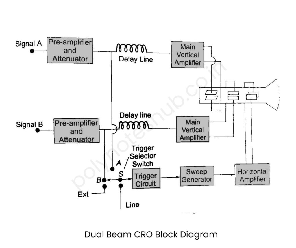
Here is the block diagram of dual beam oscilloscope –

- Signal Input: The Dual Beam CRO includes two independent input channels: Signal A and Signal B. These signals are measured and analyzed independently using the oscilloscope. Each signal is processed independently before being presented on the screen, allowing the oscilloscope to study and compare two waveforms at the same time.
- Pre-Amplifier and Attenuator: The input signals are first routed through a preamplifier and attenuation stage. The pre-amplifier strengthens the signal while preserving signal integrity, resulting in reliable measurements. The attenuator regulates signal amplitude, preventing distortion and enabling for accurate analysis of both high and low-amplitude signals.
- Delay Line: After amplification and attenuation, the signals are sent over delay lines. These delay lines ensure that the signals reach the vertical amplifier somewhat after the trigger signal. This delay allows the oscilloscope to collect and display the signal waveform from the start, resulting in accurate visualization of transient events.
- Main Vertical Amplifier: The delayed signals are subsequently transferred through the primary vertical amplifiers. These amplifiers amplify the signals and alter the gain to ensure optimal presentation on the screen. The two separate amplifiers allow for independent control of both input signals, ensuring that they are shown with the proper amplitude and phase connection.
- Trigger Circuit and Selector Switch: The trigger circuit is responsible for ensuring that the waveform display remains stable. It guarantees that the oscilloscope draws the waveform at the same position in each cycle, making the signal appear consistent. The trigger selector switch allows the user to specify which signal (A or B) to be utilized as the trigger source, providing greater flexibility in waveform analysis.
- Sweep Generator: The sweep generator sets up a time base for the oscilloscope display. It generates a sawtooth waveform, which travels the electron beam horizontally across the screen at a steady speed. This ensures that waveforms are shown correctly across time, allowing for accurate assessment of signal frequency and duration.
- Horizontal Amplifier: The horizontal amplifier receives and amplifies the sweep signal from the sweep generator before transmitting it to the CRT’s horizontal deflection plates. This ensures that the electron beam moves in a clear and stable horizontal direction while retaining waveform purity and synchronization.
- Cathode Ray Tube or CRT: Finally, the processed signals appear on the CRT screen. The vertical deflection plates govern the vertical movement of the electron beam in response to amplified signals, whilst the horizontal deflection plates control the beam’s horizontal movement. The dual beam arrangement displays both signals concurrently, allowing users to compare waveforms in real time.
Dual Beam CRO Working Principle
The Dual Beam CRO uses two separate electron cannons, each of which generates an electron beam. These beams pass via separate vertical and horizontal deflection plates before being projected on the phosphor screen. The oscilloscope can function in two modes –
- Independent Mode: Each beam has its own deflection system, thus two signals can be presented independently.
- Common Mode: Both beams use the same time base, ensuring coordinated signal comparison.
Electrostatic deflection is used to regulate electron beams, which move up and down vertically and left and right horizontally. The signals are then shown on a CRT (Cathode Ray Tube) screen.
Dual Beam CRO Advantages
Here are the advantages of dual beam CRO –
- This type of CRO can display two single at a single time.
- Each input signal will get independent processing system.
- The trigger circuit and delay line ensure accurate timing.
- Useful for studying signals with modulation and phase errors.
- Helps to compare input/output waveforms in electrical circuits.
Dual Beam CRO Disadvantages
Here are the disadvantages of dual beam CRO –
- This circuit requires separate vertical amplifiers and electron beams, which makes it more expensive than a single-beam CRO.
- A dual-beam CRO requires more extensive repair and calibration than a single beam CRO.
- Both beams use the same horizontal deflection system, which may limit functioning in some situations.

