In this article, we discuss the Full Wave Rectifier and its types, Working Principles, Advantages, and Disadvantages. Welcome to Poly Notes Hub, a leading destination for Diploma Engineering Notes.
What is Full Wave Rectifier?
In full wave rectification, current flows through the load in the same direction for both half-cycles of input A.C. voltage. This can be achieved with two diodes working alternately. For the positive half-cycle of input voltage, one diode supplies current to the load; for the negative half-cycle, the other diode does so; with current being always in the same direction through the load. Therefore, a full-wave Rectifier utilizes both half-cycles of input A.C. voltage to produce the D.C. output
Types of Full Wave Rectifier
The following two circuits are commonly used for full-wave rectification:
- Centre-tap full-wave Rectifier
- Full-wave bridge rectifier
Center Tap Full Wave Rectifier
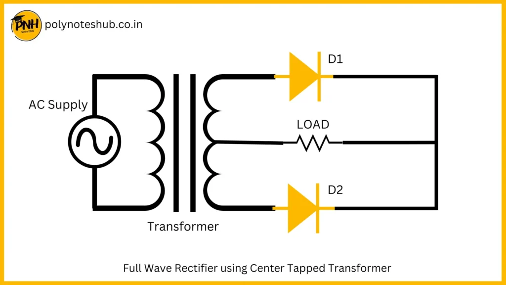
In this rectifier circuit, one center-tapped transformer is used with two diodes. These diodes are connected alternately with the secondary winding of the transformer.
Circuit Details
The circuits employ two diodes D1 and D2 as shown in Figure. A center-tapped secondary winding is used with two diodes connected so that each uses one half-cycle of input A.C. voltage. In other words, diode D1 utilizes the a.c. the voltage appearing across the upper half of the secondary winding for rectification while diode D2 uses the lower half winding of the secondary.
Here Is the circuit diagram of the Center Tap Full Wave Rectifier Circuit

Working Principle
During the positive half cycle of the input voltage, the diode D1 becomes forward-biased and conducts current. At this condition the diode D2 at reverse biased, so it does not conduct any current. So, we get the output at this condition.
During the negative half cycle of the input voltage, the diode D2 becomes forward-biased and conducts current. At this condition the diode D1 at reverse biased, so it does not conduct any current. So, we get the output at this condition. By this process, full cycle is rectified in this circuit.
Disadvantages
- It is difficult to locate the center tap on the secondary winding.
- The A.C. output is small as each diode utilizes only one-half of the transformer’s secondary voltage.
- The diodes used must have high peak inverse voltage.
Full Wave Bridge Rectifier
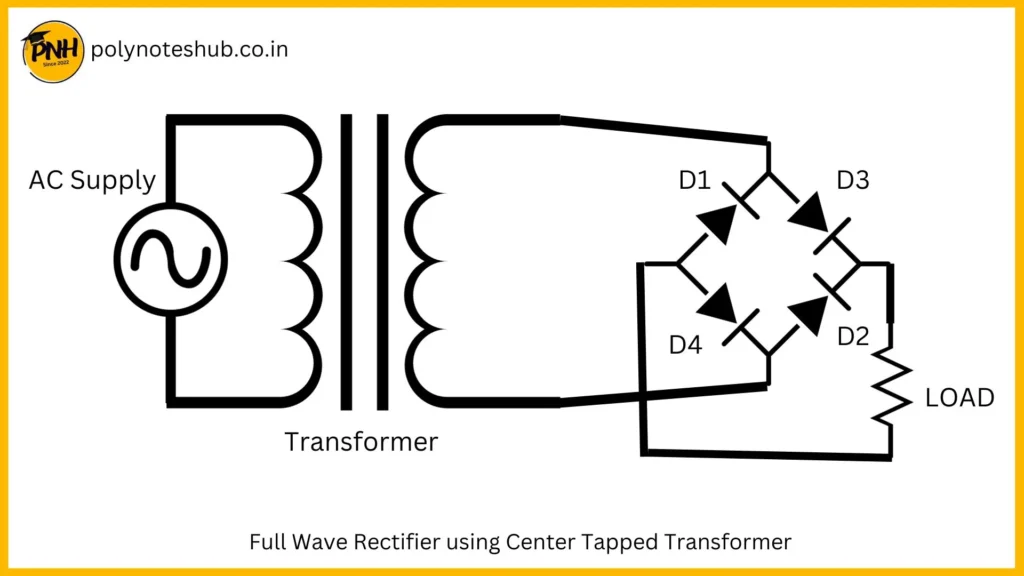
In this type of rectifier circuit, the center-tapped transformer is not used. A normal two-port transformer is used and a diode bridge is also.
Circuit Details
The need for a center-tapped power transformer is eliminated in the bridge rectifier. It contains four diodes D1, D2, D3, and D4, and is connected to form a bridge as shown in Figure. The supply to be rectified is applied to the diagonally opposite ends of the bridge through the transformer. Between the other two ends of the bridge, the load resistance is connected.

Working Principle
During the positive half-cycle of the input A.C. signal diode D3 and D4 become forward biased and D1 and D2 become reverse based. At this condition, only D3 and D4 conduct current and the other two diode does not conduct any amount of current. So, we get the output at the load.
During the negative half-cycle of the input A.C. signal diode D3 and D4 become reverse biased and D1 and D2 become forward based. At this condition, only D1 and D2 conduct current, and the other two diode does not conduct any amount of current. So, we get the output at the load.
By this process, we get full wave rectification in this circuit.
Advantages
- The need for center-tapped transformer is eliminated.
- The output is twice that of the center-tap circuit for the same secondary voltage
- The PIV is one-half that of the center tap circuit.
Disadvantages
- It requires four diodes
- Voltage drop can be seen in this circuit.
Conclusion | Diploma Engineering Notes | Poly Notes Hub
Our Poly Notes Hub provides syllabus-wise notes for polytechnic or diploma engineering students of streams like Electrical Engineering, Electronica and Tele-Communication Engineering, Electronics Engineering, Electrical and electronics Engineering, Electronics & Instrumentation Engineering, and Computer Science & Technology. Our website is updating day by day so keep in touch with us for new and syllabus-wise notes and topic which helps you all to do any task regarding diploma engineering.

