In this note, we are going to know about Keyboard Interfacing with 8051 Microcontroller. Welcome to Poly Notes Hub, a leading destination for engineering notes for diploma and degree engineering students.
Author Name: Arun Paul.
Keyboard Interfacing with 8051 Microcontroller
Keyboard Interfacing with 8051 Microcontroller allows the microcontroller to receive keyboard input, which is frequently used in embedded applications. Interfacing with this system is often done using a 4×4 matrix keyboard. The keyboard is made up of rows and columns arranged in a switch matrix. When a key is pressed, a link between a specified row and column is established, which the microcontroller can detect.
In this configuration, the keyboard functions as a grid of switches organized in rows and columns. When a key is pressed, it connects a certain row and column, allowing the microcontroller to determine the key’s location. The microcontroller determines which key is pushed by sequentially scanning these rows and columns.
Importance of This Microcontroller Project –
- Enables data or command input for interactive embedded systems.
- Used in ATMs, digital locks, calculators, and control panels.
- Simple and affordable input solution.
- Applicable to other microcontrollers like AVR, PIC, or ARM.
- Foundation for projects like touchpads or advanced security systems.
About 8051 Microcontroller
The 8051 microcontroller is a popular 8-bit microcontroller designed by Intel in 1980. It is part of the MCS-51 family and is well-known for its simplicity, adaptability, and wide application in embedded systems. The 8051 microcontroller is widely used in industrial, commercial, and consumer applications including home appliances, automation systems, and robots.
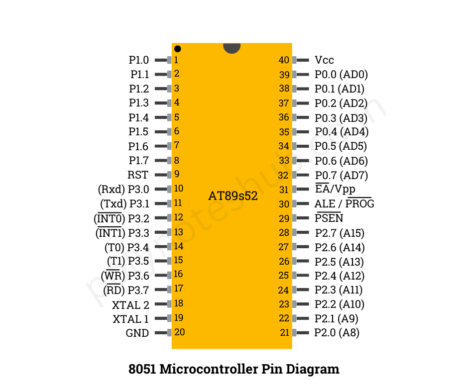
Pin Diagram of 8051 Microcontroller

The 8051 microcontroller is widely used in embedded systems. It has a total of 40 pins, each serving a specific function. Here’s a brief description of the function of the 8051 Microcontroller Pin Diagram:
- VCC (Pin 40): Supply voltage input (+5V) for the microcontroller.
- GND (Pin 20 and 40): Ground reference for the microcontroller.
- P0.x (Pin 32-39): General-purpose bidirectional I/O pins of Port 0.
- P1.x (Pin 1-8): General-purpose bidirectional I/O pins of Port 1.
- P2.x (Pin 21-28): General-purpose bidirectional I/O pins of Port 2.
- P3.x (Pin 10-17): General-purpose bidirectional I/O pins of Port 3.
- RST (Pin 9): External reset input. A low pulse on this pin resets the microcontroller.
- ALE/PROG (Pin 30): Address Latch Enable (ALE) and Program Pulse Input. Used to demultiplex the address and data during external memory access.
- PSEN (Pin 29): Program Store Enable. Used to enable external ROM memory.
- EA/VPP (Pin 31): External Access Enable (EA) and programming supply voltage (VPP) during EPROM programming.
- XTAL1 (Pin 19): Input for connecting an external crystal oscillator or resonator.
- XTAL2 (Pin 18): Output of the crystal oscillator or resonator.
- RD (Pin 39): Read control signal for external memory.
- WR (Pin 37): Write control signal for external memory.
- T0 (Pin 18): Timer 0 external input.
- T1 (Pin 17): Timer 1 external input.
- INT0 (Pin 12): External interrupt 0 input.
- INT1 (Pin 13): External interrupt 1 input.
- TXD (Pin 10): Serial transmission data.
- RXD (Pin 11): Serial reception data.
- T2EX (Pin 1): Timer 2 external count input.
- T2 (Pin 2): Timer 2 output/input.
- EX0 (Pin 3): External interrupt 0 enable input.
- EX1 (Pin 4): External interrupt 1 enable input.
- VCC (Pin 20): Supply voltage input (+5V) for the microcontroller.
Components Required for the keyboard Interfacing with 8051 Microcontroller
- 8051 microcontroller (e.g., AT89C51 or AT89S52)
- 4×4 matrix keyboard
- Pull-up resistors for rows
- 16×2 LCD Module (optional, for display)
- External oscillator (if required for the 8051)
- Capacitors and reset circuit for the microcontroller
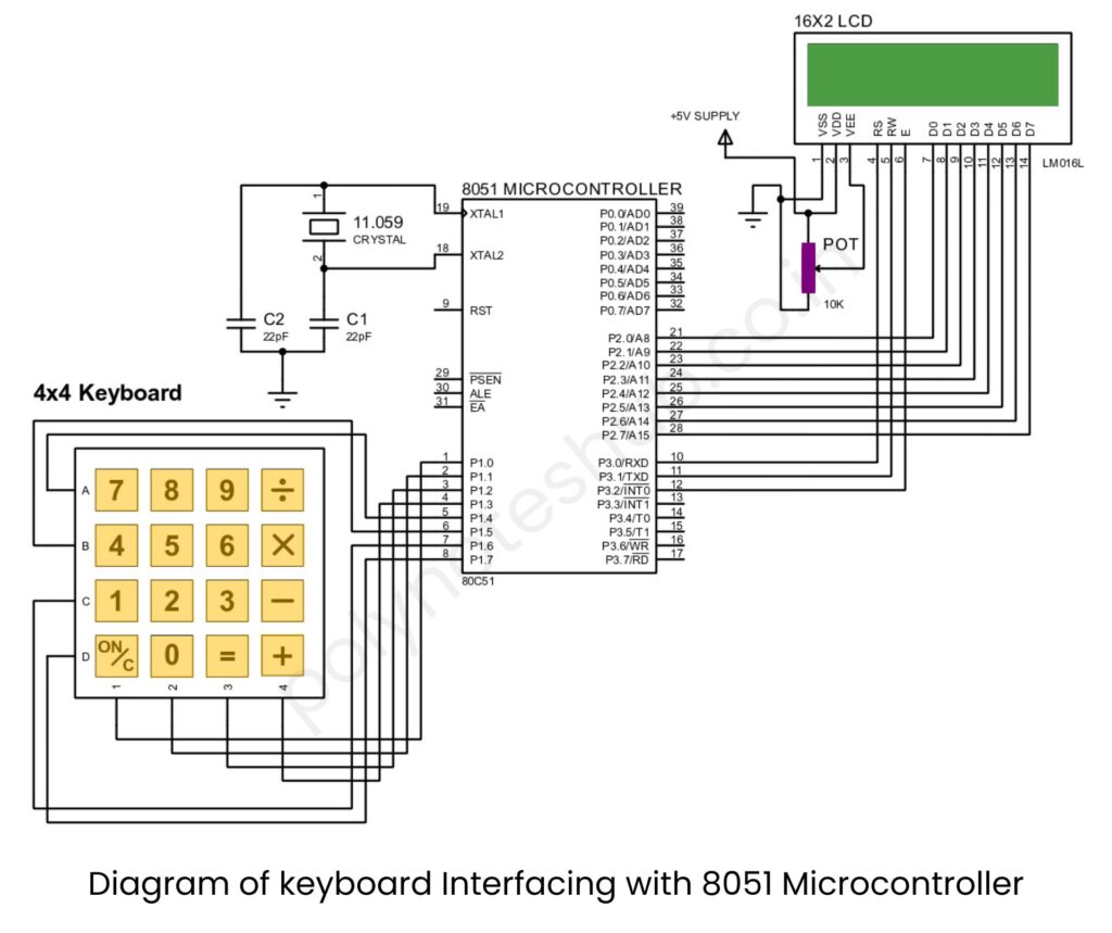
Connection Diagram of keyboard Interfacing with 8051 Microcontroller

Keyboard to 8051:
- Connect the columns of the keyboard (C1, C2, C3, C4) to Port P1.0 to P1.3 of the 8051.
- Connect the rows of the keyboard (R1, R2, R3, R4) to Port P1.4 to P1.7 of the 8051.
- Pull-up resistors are connected to the row lines.
8051 Configuration:
- External oscillator is connected to XTAL1 and XTAL2 (typically 12 MHz crystal oscillator with capacitors).
- Reset pin (Pin 9) is connected via a resistor and capacitor circuit to ensure proper initialization.
LCD to 8051:
- Connect data pins of the LCD to Port P2 of the 8051.
- Connect control pins (RS, RW, and EN) to Port P3.
Keyboard Interfacing with 8051 Microcontroller C Program
Here is the keyboard interfacing with 8051 program. The program was written in Embedded C. It scans the keyboard, detects key presses, and can optionally display the pressed key on an LCD.
#include <reg51.h>

// Define Ports
#define KEYBOARD P1  // Port for keyboard
#define LCD P2       // Port for LCD

sbit RS = P3^0;  // Register Select for LCD
sbit RW = P3^1;  // Read/Write for LCD
sbit EN = P3^2;  // Enable for LCD

// Function Prototypes
void delay_ms(unsigned int ms);
void lcd_init();
void lcd_cmd(unsigned char cmd);
void lcd_data(unsigned char data);
void lcd_display(char *text);
unsigned char key_scan();
void key_map(unsigned char key);

void main() {
    unsigned char key;
    lcd_init();             // Initialize LCD
    lcd_display("Key Pressed:"); // Display message on LCD
    while (1) {
        key = key_scan();   // Scan for key press
        if (key != 0xFF) {  // If a key is detected
            key_map(key);   // Map and display the key
        }
    }
}

// Key Scan Function
unsigned char key_scan() {
    unsigned char row, col;
    KEYBOARD = 0xF0;  // Set rows as input, columns as output
    for (row = 0; row < 4; row++) {
        KEYBOARD = ~(0x10 << row); // Set one row low at a time
        col = KEYBOARD & 0x0F;    // Read columns
        if (col != 0x0F) {        // If a column is low
            return (row << 4) | col; // Return row and column data
        }
    }
    return 0xFF; // No key pressed
}

// Key Mapping Function
void key_map(unsigned char key) {
    unsigned char row = key >> 4;
    unsigned char col = key & 0x0F;
    unsigned char key_pressed;
    // Key Mapping (Example for 4x4 keyboard)
    unsigned char keys[4][4] = {
        {'1', '2', '3', 'A'},
        {'4', '5', '6', 'B'},
        {'7', '8', '9', 'C'},
        {'*', '0', '#', 'D'}
    };
    if (col == 0x0E) key_pressed = keys[row][0];
    else if (col == 0x0D) key_pressed = keys[row][1];
    else if (col == 0x0B) key_pressed = keys[row][2];
    else if (col == 0x07) key_pressed = keys[row][3];
    lcd_cmd(0xC0); // Move to second line
    lcd_data(key_pressed); // Display the pressed key
}

// LCD Functions (Initialization, Command, and Data)
void lcd_init() {
    lcd_cmd(0x38);  // 8-bit mode, 2 lines
    lcd_cmd(0x0C);  // Display ON, Cursor OFF
    lcd_cmd(0x01);  // Clear Display
    lcd_cmd(0x06);  // Increment Cursor
}

void lcd_cmd(unsigned char cmd) {
    LCD = cmd;
    RS = 0;
    RW = 0;
    EN = 1;
    delay_ms(2);
    EN = 0;
}

void lcd_data(unsigned char data) {
    LCD = data;
    RS = 1;
    RW = 0;
    EN = 1;
    delay_ms(2);
    EN = 0;
}

void lcd_display(char *text) {
    while (*text) {
        lcd_data(*text++);
    }
}

void delay_ms(unsigned int ms) {
    unsigned int i, j;
    for (i = 0; i < ms; i++)
        for (j = 0; j < 1275; j++);
}
Keyboard Interfacing with 8051 Microcontroller Assembly Program
ORG 0000H

; Define Ports
KEYBOARD EQU P1   ; Port for keyboard
LCD EQU P2        ; Port for LCD
RS EQU P3.0       ; Register Select
RW EQU P3.1       ; Read/Write
EN EQU P3.2       ; Enable

; Function Prototypes
CALL LCD_INIT
CALL LCD_DISPLAY

MAIN:
    CALL KEY_SCAN    ; Scan for key press
    CJNE A, #0FFH, DISPLAY_KEY ; If key is detected, display
    SJMP MAIN        ; Loop continuously

DISPLAY_KEY:
    CALL KEY_MAP     ; Map the key
    CALL LCD_CMD     ; Move cursor to second line
    CALL LCD_DATA    ; Display the key
    SJMP MAIN        ; Repeat

; Key Scan Function
KEY_SCAN:
    MOV A, #0F0H
    MOV P1, A       ; Set rows as input, columns as output
    MOV R0, #00H    ; Row counter
SCAN_LOOP:
    MOV A, #0EFH    ; Activate first row
    RL A
    MOV P1, A
    MOV A, P1       ; Read column
    ANL A, #0FH
    CJNE A, #0FH, KEY_DETECTED
    INC R0
    CJNE R0, #04H, SCAN_LOOP
    MOV A, #0FFH    ; No key pressed
    RET
KEY_DETECTED:
    MOV A, R0
    SWAP A
    ORL A, P1
    RET

; Key Mapping Function
KEY_MAP:
    ; Mapping logic (4x4 keypad example)
    MOV DPTR, #KEY_TABLE
    MOVC A, @A+DPTR
    RET

KEY_TABLE:
    DB '1', '2', '3', 'A'
    DB '4', '5', '6', 'B'
    DB '7', '8', '9', 'C'
    DB '*', '0', '#', 'D'

; LCD Functions
LCD_INIT:
    MOV A, #38H  ; 8-bit mode, 2 lines
    CALL LCD_CMD
    MOV A, #0CH  ; Display ON, Cursor OFF
    CALL LCD_CMD
    MOV A, #01H  ; Clear Display
    CALL LCD_CMD
    MOV A, #06H  ; Increment Cursor
    CALL LCD_CMD
    RET

LCD_CMD:
    MOV LCD, A
    CLR RS
    CLR RW
    SETB EN
    CALL DELAY_MS
    CLR EN
    RET

LCD_DATA:
    MOV LCD, A
    SETB RS
    CLR RW
    SETB EN
    CALL DELAY_MS
    CLR EN
    RET

LCD_DISPLAY:
    MOV DPTR, #MSG
    MOV R0, #00H
DISPLAY_LOOP:
    MOV A, R0
    MOVC A, @A+DPTR
    JZ DISPLAY_END
    CALL LCD_DATA
    INC R0
    SJMP DISPLAY_LOOP
DISPLAY_END:
    RET

MSG: DB 'Key Pressed:', 00H

; Delay Function
DELAY_MS:
    MOV R2, #50H
DELAY_LOOP1:
    MOV R1, #255
DELAY_LOOP2:
    DJNZ R1, DELAY_LOOP2
    DJNZ R2, DELAY_LOOP1
    RET

END
