Programmable Logic Control by Poly Notes Hub | Important topic for Diploma Engineering Notes or Engineering Notes.
What is PLC or Programmable Logic Control?
A Programmable Logic Control is an industrial system that has been used to control industrial manufacturing like factory assembly lines, machines, robotics arms or devices, or other kind of activity that is very important to the industry to increase productivity.
It is a digital computer used for the automation of electromechanical processes. These are used in many industries and machines. Unlike general-purpose computers, the PLC is designed for multiple input and output arrangements, extended temperature ranges, immunity to electrical noise, and resistance to vibration and impact.
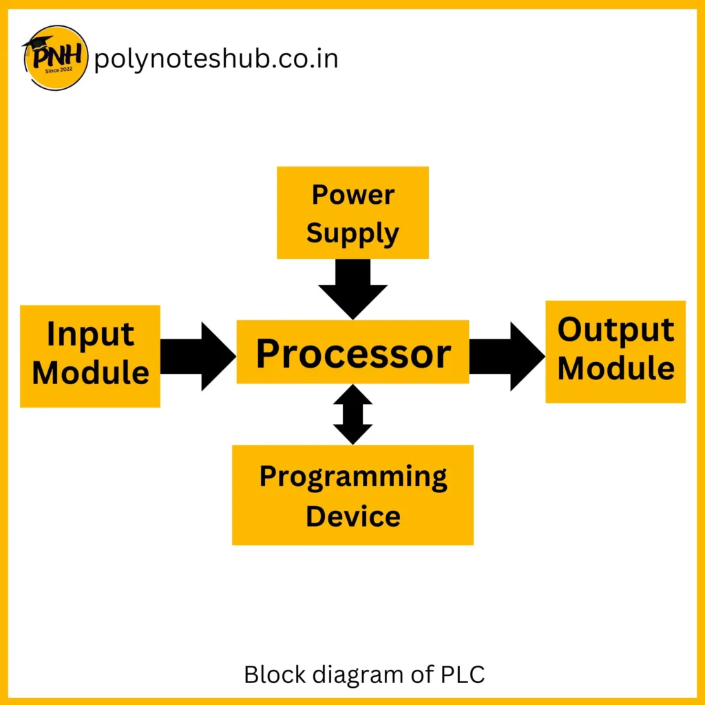
Block diagram of PLC
Below shows the typical block diagram of the system. Basic parts of the system are
- Processor or CPU (Central Processing Unit)
- Input Module
- Output Module
- Power Supply system
- Programming Device

About Each block
All PLC’s has same basic components. These works together to bring information into the PLC from the field, evaluate that information and send information back out to the various field. Without any of these major components, the PLC will fail to function properly.
Below we describes the functions of each and every component of the system.
Processor or CPU
The brain of the Programmable Logic Control has RAM, ROM, and user memory. It is also the heart of the system. The Processor controls monitors and all operations within the system. It makes a decision and executes the task according to the logic. The function of the CPU is to store and run the PLC software programs. It also interfaces with the Co-processor Modules, the I/O Modules, the peripheral device, and runs diagnostics.
Input and Output Module
The input module is the mediator or connector between the input devices and the processor. It is used to convert the analog signal into digital form.
Also, the output module is the mediator or connector between the output devices and the processor. It is used to convert the digital signal to analog form.
Power Supply
It provides power to all the sections of the whole system like the processor, input and output module, etc. The power supply module is located in the system module rack. It is supplied by single phase 120V or 240V AC line power that powers the system.
Memory Section
It is that type of section where all the data and instruction is stored. Two types of memory have been using in the system User memory and Data memory. Data memory is used to store data and User memory is used for the user’s application program.
Programming Device
It is that type of device that is used to upload the user program or data or instruction into the system. It is also used to load and reload load the ladder logic instruction.
Basic Operation of PLC
The operation of it, is very simple. The processor makes decisions based on the ladder logic program which is written by the user. To use the program properly, the PLC must communicate with the various field devices it monitors and controls. It then compares the actual conditions of the field devices with what the program instructs them to do and updates the output devices accordingly.
The operation sequences are as follows:
- The input switch is pressed.
- The input module places a “1” in the input data table.
- The ladder logic program sees the “1” and causes a “1” to be put into the output data table.
- The output data table causes the output module to energize the associated point.
- The output device energizes.
Merits or Advantages
- Fast operating time
- Wide range of control application
- It is capable to communicate with computer.
- Small in size.
- Reliability is also high
Demerits or Disadvantages
- It has too much connecting wires.
- Difficult to find out errors.
- Has fixed circuit operation.
Applications of PLC
Used in
- Traffic light system
- Automatic transfer switch
- Robotics
- Medical Instruments
- Industrial manufacturing
Difference between PLC and PC
| PLC | PC |
|---|---|
| 1. It contains various diagnostics features. | 1. It contains few diagnostics features. |
| 2. It comes with I/O modules, available for different voltage level. | 2. Computers can interface with external equipment using specific circuit cards. |
| 3. It can easily interfaced with hundreds of I/O lines. | 3. No I/O lines are fixed and comparatively lesser. |
Conclusion | Diploma Engineering Notes | Poly Notes Hub
Our Poly Notes Hub provides syllabus-wise notes for polytechnic or diploma engineering students of streams like Electrical Engineering, Electronics Engineering, Electrical & Electronics Engineering, Electronics & Instrumentation Engineering, and Computer Science & Technology. Our website is updating day by day so keep in touch with us for new and syllabus-wise notes and topic which helps you all to do any task regarding to diploma engineering.

