In this article, Poly Notes Hub discusses the Rectifier circuit and its types, working, and applications.
What is Rectifier?
It is a type of electronic circuit which is basically used to convert Alternating Current (AC) to Direct Current (DC). The opposite operation is done by the Inverter circuit.
This type of circuit is used in different kind of electronics like Adapter, Mobile Charger, Laptop Charger, Voltage Multiplier, and Modulator or De-Modulator Circuit. We can say that rectifier circuit is very important and essential part of any electronics circuit where direct current is the main power source of the circuit. So, we have to convert the AC supply to DC signal by using the rectifier circuit.
Types of Rectifier
There are two types of rectifier circuit
- Half Wave Rectifier
- Full Wave Rectifier
Half Wave Rectifier
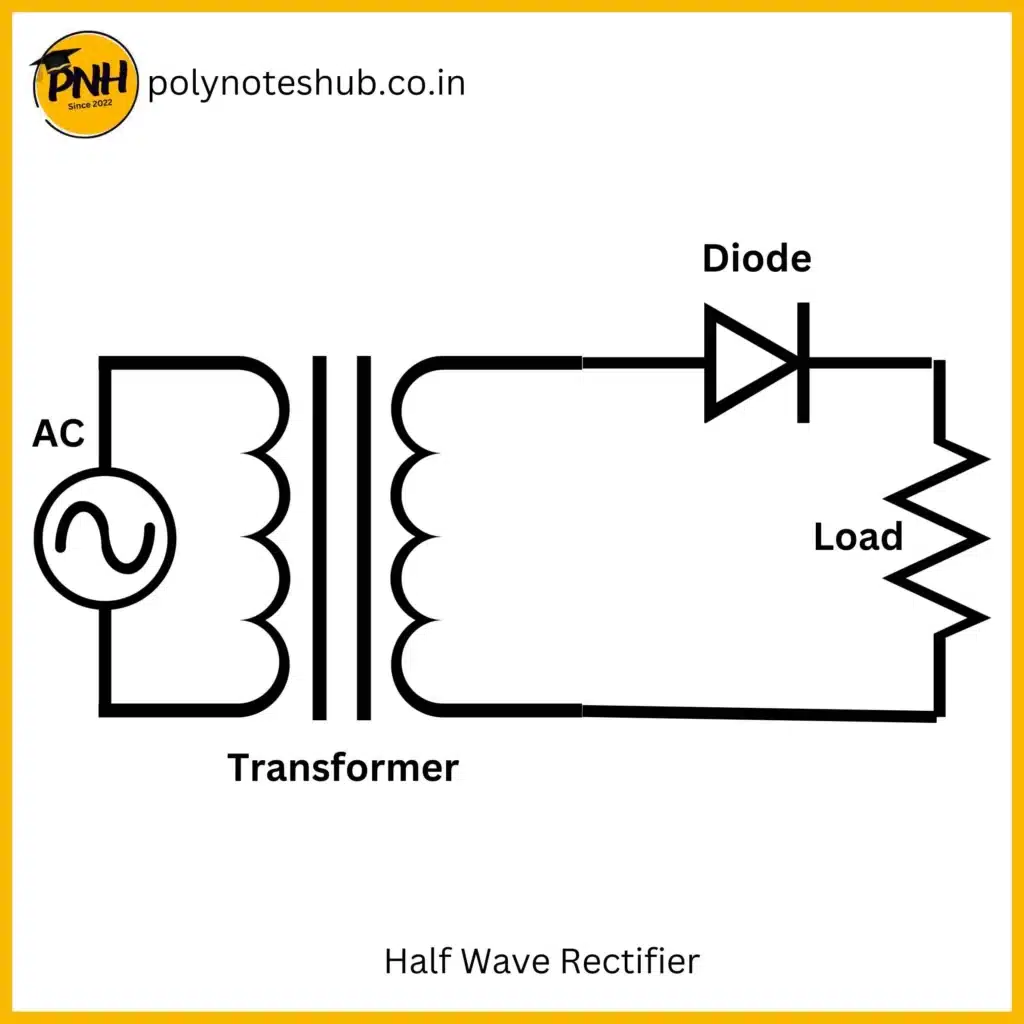
In the half-wave rectification, the rectifier conducts current only during the positive half cycles of input a.c. supply. The negative half cycles of a.c. supply are suppressed that is during negative half cycles, no current is conducted and hence no voltage appears at the load. Therefore, the current always flows in one direction ( i.e. D.C. ) through the load after every half cycle.

Above is the circuit diagram of the half-wave rectifier. In the circuit, where a single crystal diode acts as a half-wave rectifier. The a.c. supply to be rectified is applied in series with the diode and load resistance. Generally, a.c. supply is given through the transformer. The use of a transformer has two advantages. Firstly, it allows us to step up and step down the a.c. input voltage as the situation demands. Secondly, the transformer isolates the rectifier circuit from the power line and thus reduces the risk of electric shock.
Full Wave Rectifier
There two different kind of circuit which are performed full wave rectification
- Using a Centre Tapped Transformer
- Using a diode bridge circuit
These two circuits are used to produce full wave rectification. In full wave rectification, current can be conducted during both of the cycles (Positive or Negative Half Cycle) of the input signal.
So, we can say that Full Wave Rectifier is that kind of rectification circuit which can convert the complete cycle of alternating current (AC) into direct current (DC). Full wave rectifier can design in two ways-
Using Centre Tapper Transformer
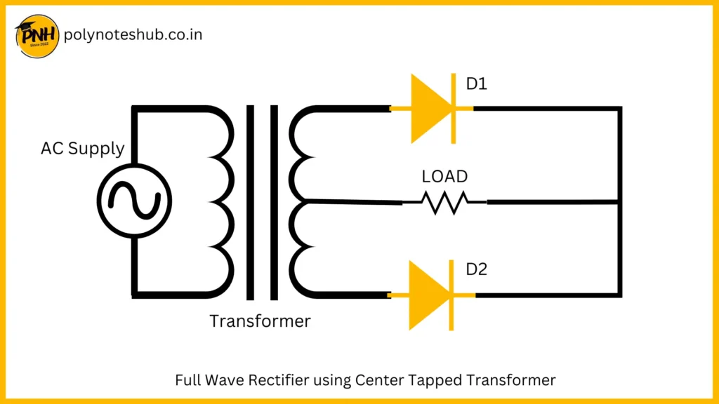
In this circuit a center tapped transformer is used. The alternating source is connected at the primary of center tapped transformer and two diode are connect at the secondary of the transformer in alternative direction. The output is collected from the center of the center tapped transformer. During the positive half cycle diode D1 become forward biased and D2 become reverse biased and starts conducting current. During the negative half cycle, diode D2 become forward biased and D1 become reverse biased and conduct current. By this way, both of the cycle or full cycle is rectified by this circuit. Below shows the circuit diagram of full wave rectifier circuit with center tapped transformer.

Using Diode Bridge Circuit
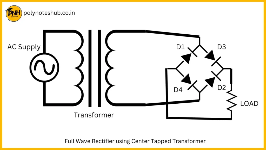
In this circuit, a diode bridge is used for rectification process. In this circuit, there is no center tapped transformer. A normal transformer is used here. The source is connected to the primary winding and the diode bridge is connected at the secondary of the transformer. The diode bridge has 4 diode (D1, D2, D3 and D4). In the diode bridge, two diode (D1 and D2) become forward biased during the positive half cycle and other two (D3 and D4) become forward biased during the negative half cycle. By this process, both of cycles are rectified in this circuit. Below shows the circuit diagram of the full wave rectifier using Diode Bridge.

Working of Rectifier
The working of rectifier circuit is basically based on the diode’s biasing process. As we know that PN Junction Diode is only conduct current during the forward biasing. So, if the PN Junction Diode is in reverse biased then the diode does not conduct current.
Below, we discuss about the working of Half Wave Rectifier circuit.
The a.c. voltage across the secondary winding changes polarities after every half cycle. During the positive half cycle of input a.c. voltage, end A becomes positive w.r.t. B. This makes the diode forward biased and hence it conducts current. During the negative half-cycle, end A becomes negative w.r.t. B. Under this condition, the diode becomes reverse biased and it does not conduct current. Therefore, current flows through the diode during the positive half cycles of the input a.c. supply.
Applications of Rectifier
Some common applications of rectifier circuit is given below
- Used in Mobile Charger, Laptop Charger, Adapter.
- Used in Modulator and De-modulator
- Also Used in Voltage Multiplier
Conclusion | Diploma Engineering Notes | Poly Notes Hub
Our Poly Notes Hub provides syllabus-wise notes for polytechnic or diploma engineering students of streams like Electrical Engineering, Electronics Engineering, Electronics and Tele-Communication Engineering, Electrical and electronics Engineering, Electronics & Instrumentation Engineering, and Computer Science & Technology. Our website is updating day by day so keep in touch with us for new and syllabus-wise notes and topic which helps you all to do any task regarding diploma engineering.


