In this note, we are going to know about Single Phase PWM Inverter. About its specifications, circuit diagram, operation, advantages, and applications. Welcome to Poly Notes Hub, a leading destination for engineering notes for diploma and degree engineering students.
Author Name: Arun Paul.
What is Single Phase PWM Inverter?
A Single Phase PWM Inverter is an electrical device that converts DC (Direct Current) to AC (Alternating Current) by employing pulse width modulation (PWM) techniques to efficiently regulate the output voltage and frequency.
Specifications of Single Phase PWM Inverter
Here we have listed some common parameters and values of this circuit –
| Parameters | Values |
|---|---|
| Input Voltage | Typically 12V, 24V, or 48V DC |
| Output Voltage | 110V or 230V AC (RMS) |
| Output Frequency | 50Hz or 60Hz |
| Switching Frequency | Ranges from 2 kHz to 20 kHz |
| Efficiency | 85% – 95% |
| Total Harmonic Distortion (THD) | < 5% (depends on filtering) |
| Load Capacity | Varies from a few watts to several kilowatts |
| Control Method | Sinusoidal PWM (SPWM) or Modified Sine Wave |
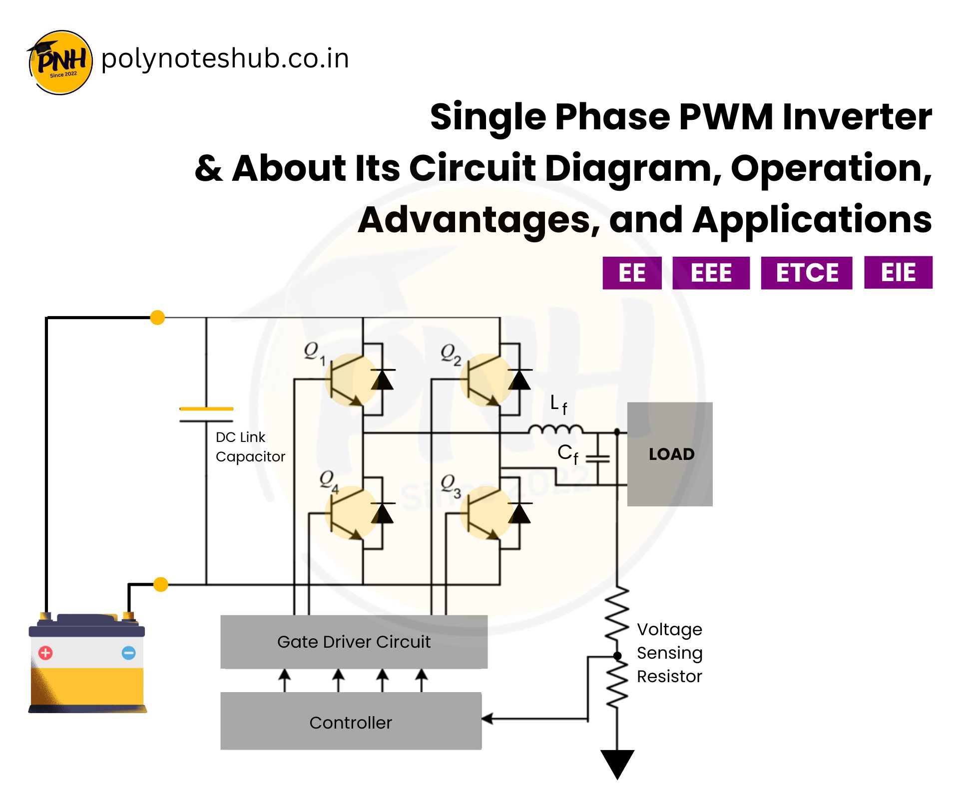
Single Phase PWM Inverter Circuit Diagram

Circuit Description of this type of inverter
- DC Source: It is provides the input DC voltage.
- H-Bridge (Four MOSFETs/IGBTs): In this section, there are 4 power switches (Q1, Q2, Q3, Q4) which are enabling bidirectional current flow.
- Gate Driver Circuit: This circuit is use to amplifies and isolates control signals to drive the MOSFETs or IGBTs.
- Controller (Microcontroller or PWM Generator): Used to Generates PWM signals to control the switching sequence of the circuit.
- Load (AC Load): The output AC voltage is applied to the load and collected from it..
- Filtering Components (Not Shown in Diagram): An additional LC filters may be used to smoothen the AC output.
Single Phase PWM Inverter Operation
Here in step by step, we have listed single phase PWM inverter working principle –
1. PWM Signal Generation
- A microcontroller (such as Arduino, PIC, or DSP) generates PWM signals with a specific frequency.
- These signals are fed to the Gate Driver, which amplifies the signals to drive the MOSFETs/IGBTs in the H-Bridge.
2. H-Bridge Switching Operation
- The inverter circuit operates in two half-cycles to create an AC waveform.
- The H-Bridge circuit consists of four switches (Q1, Q2, Q3, and Q4).
- These switches operate in a complementary manner to generate alternating voltage across the load.
3. Two Operating Modes in One Cycle
- First Half-Cycle (Positive Output Voltage): Q1 and Q4 turn ON, while Q2 and Q3 remain OFF. This allows current to flow from the DC source → Q1 → Load → Q4 → Ground, producing a positive half-cycle of the AC waveform.
- Second Half-Cycle (Negative Output Voltage): Q2 and Q3 turn ON, while Q1 and Q4 remain OFF. This reverses the current flow (DC source → Q3 → Load → Q2 → Ground), producing a negative half-cycle of the AC waveform.
- By rapidly switching the MOSFETs using PWM signals, the inverter generates an approximate AC waveform from the DC supply.
4. PWM Control for Output Regulation
- The duty cycle of the PWM signal determines the effective output voltage of the inverter.
- A sinusoidal PWM (SPWM) technique can be used to approximate a sine wave, reducing harmonic distortion.
Output Voltage Equation
The fundamental RMS output voltage (Vo(rms)) equation of single phase PWM inverter is given by –

Where;
- Ma = Modulation Index, which is the ratio of peak modulating signal voltage to DC input voltage ( Vm/Vdc ).
- Vdc = DC Voltage
- Vm = Modulation voltage peak value.
For SPWM of Sinusoidal Pulse Width Modulation, the maximum output RMS voltage is –

Output Frequency Equation
The output frequency (fo) of the inverter is controlled by the frequency of the reference (modulating) signal. It is given by –

Where;
- fo = Output frequency.
- fm = Frequency of the modulation signal.
Single Phase PWM Inverter Advantages
Here we have listed some advantages of single phase PWM inverter –
- It has higher efficiency ( 85% – 95% ) compare to square wave inverter circuit.
- This circuit has better voltage regulation because of PWM controller.
- Reduces harmonics distortion and produce smoother AC output.
- The design of the circuit is compact and light in weight. So, this circuit can use in portable applications also.
- The output voltage is enough for used purposes.
Single Phase PWM Inverter Applications
Here we have listed some applications of single phase PWM inverter –
- Used in UPS (Uninterruptible Power Supply) Systems
- Used in Solar Power Systems
- Used in Electric Vehicle Drives
- Used in Induction Heating
- Used in Speed Control of AC Motors
- Used in Household & Industrial Power Backup

