In this note, we are going to learn about the Block Diagram of FSK Modulator and Demodulator. Welcome to Poly Notes Hub, a leading destination for diploma and degree engineering notes.
Author Name: Arun Paul.
What is FSK or Frequency Shift Keying Modulation?
Frequency Shift Keying or FSK is a form of digital communication technique in which the modulation signal shifts the output frequency between predeterminant values.
There are two form of FSK
- Coherent Form: The Coherent form of FSK exists in which there is no phase discontinuity in the output signal.
- Non-coherent Form: The instantaneous frequency is shifted between two discrete values termed the mark frequency and the space frequency. This non-coherent form of FSK signal.
Advantages of FSK Signal Modulation
- BFSK or FSK is relatively easy to implement.
- It has better noise immunity than ASK Signal.
Disadvantages of the FSK Signal Modulation
- The major disadvantage or drawback is that it requires higher bandwidth. There, it is extensively used in low-speed modems having a bit rate below 1200 bits per second.
Block Diagram of FSK Modulator and Demodulator
Block Diagram of FSK Modulator
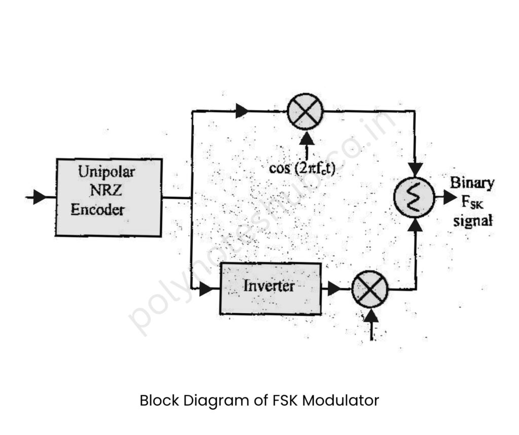
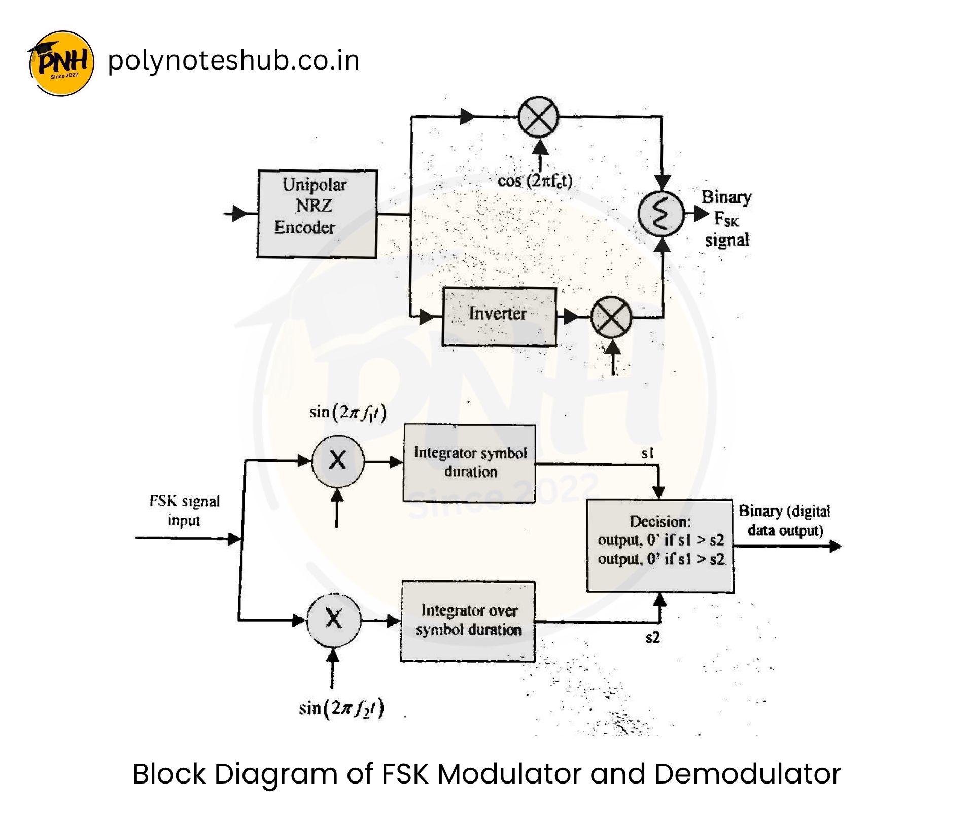
The block diagram depicts a Frequency Shift Keying (FSK) Modulator, which turns binary data into an analog signal by altering the carrier frequency. The input binary data is first transformed to unipolar NRZ format, where ‘1’ represents a high level and ‘0’ represents a low level.

This signal is split into two paths: one travels directly to a multiplier with a carrier of frequency f₁, and the other passes through an inverter before proceeding to a second multiplier with a carrier frequency f₂. Depending on the input bit, only one path can be active at any given time. The outputs of both multipliers are combined to form the final FSK signal, which alternates between two frequencies dependent on the binary input.
Block Diagram of FSK Demodulator
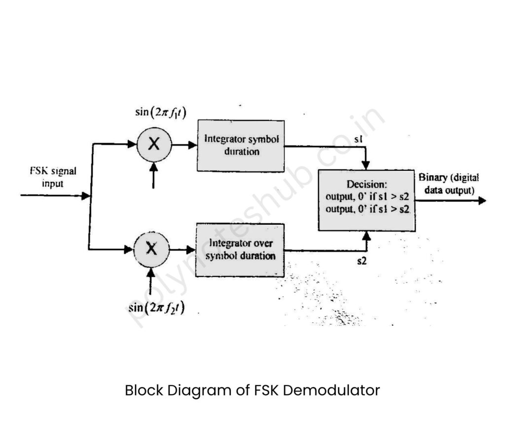
A coherent demodulator of FSK consists of two correlators, each comprising a multiplier followed by an integrator. These correlators are separately tuned to different carrier frequencies f1 & f2.

The objective of the comparator is to look for the likeness in the outputs from the two integrators and make a decision in favour of 0 or 1. For example, if the output s1 is greater than s2, 1is decided and vice versa. It is called coherent as the operation of the detector depends on both phase and time synchronization. In phase synchronization, the carrier wave produced by the local oscillator is locked in phase with the one used in the modulator at the transmitter. Also, for timing synchronization, the instant at which the decision is made in the receiver must be appropriately timed with the switching instants between 0 & 1 in the transmitter.

