In this note, we are going to know How to interface 7 segment display with 8051 microcontroller. Welcome to Poly Notes Hub, a leading destination for engineering notes for diploma and degree engineering students.
Author Name: Arun Paul.
How to Interface 7 Segment Display with 8051 Microcontroller?
A 7-segment display is a simple and commonly employed electrical display device that shows decimal numbers and some alphabets. It consists of eight LEDs (segments) designated A, B, C, D, E, F, G, and a dot (DP). These portions can be turned on and off to show the desired number or character.
Interfacing a 7-segment display with an 8051 microcontroller entails controlling the segments via the microcontroller’s I/O pins. This project explains how to display digits (0-9) on a common cathode 7-segment display with an 8051.
Components Required
- 8051 Microcontroller (Ex. AT89S52)
- 7 Segment Display (Common Cathode)
- Resistors (220 Ohm)
- Power Supply (5V)
- Crystal Oscillator (11.059 MHz or 12 MHz)
- Capacitors (22pF or 33pF for crystal oscillator)
- Breadboard and connecting wires
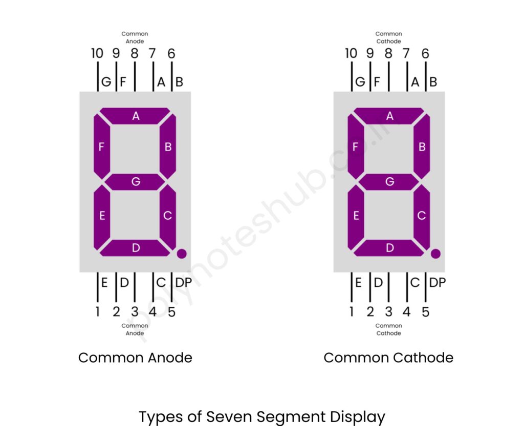
About 7 Segment Display and Types of Seven Segment Display
A 7 segment display is a visual device composed of seven individual segments arranged in a pattern that can display numerals (0-9) and some alphabetic characters. These segments are arranged in a specific pattern resembling the number “8” and are controlled by providing power to different combinations of segments to form different numbers or characters. Each segment can be individually illuminated to display the desired symbol.
There are two types of seven segment display –

- Common Anode Type Seven Segment Display: In a common anode 7 segment display, all the anodes of the LED segments are connected together and tied to a common connection, while each segment’s cathode is connected separately. Anodes are the terminals through which current flows into a diode or LED when a voltage is applied. The common anode connection of 7 Segment Display is shown in the above picture. Noted: In this type of display, the common terminal should be connected with positive terminal or HIGH or LOGIC 1 and to glow each segment then those segments terminals are connected to the negative terminal or LOW or LOGIC 0.
- Common Cathode Type Seven Segment Display: In a common cathode display, all the cathodes of the LED segments are connected together and tied to a common connection, while each segment’s anode is connected separately. Cathodes are the terminals used to control the flow of current in a diode or LED. When a particular segment’s anode is provided with a positive voltage (relative to the common cathode), and the cathode is connected to ground (or a lower potential), current flows through the segment, causing it to light up. The common cathode connection of 7 Segment Display is shown in the above picture. Noted: In this type of display, the common terminal should be connected with negative terminal or LOW or LOGIC 0 and to glow each segment then those segments terminals are connected to the positive terminal or HIGH or LOGIC 1.
These displays are commonly used in digital clocks, electronic meters, and other devices where numerical or limited alphanumeric information needs to be shown.
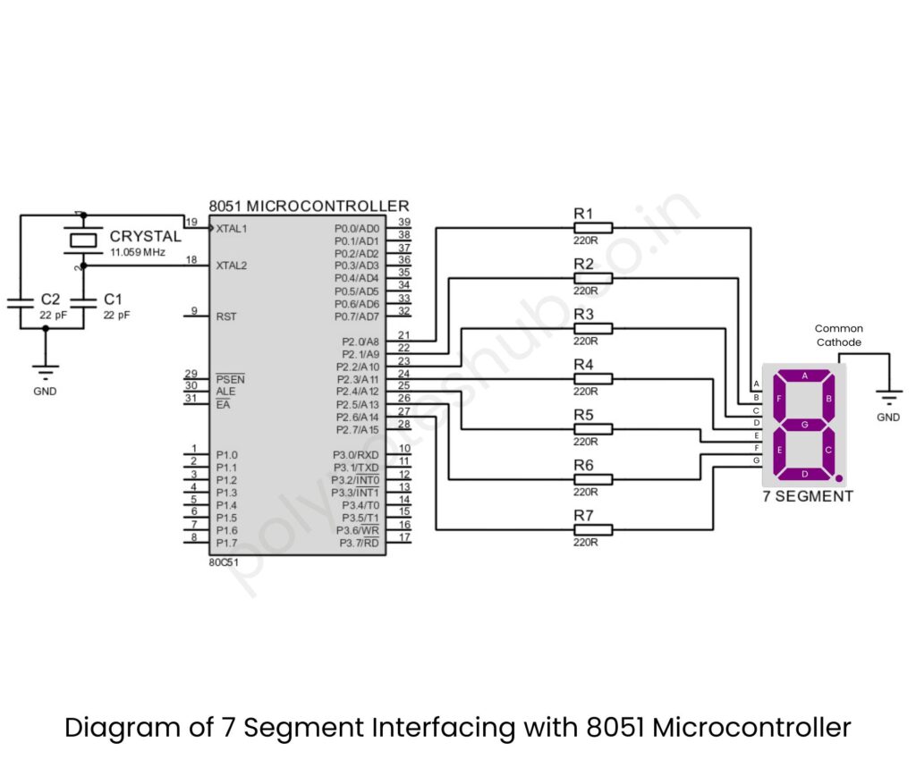
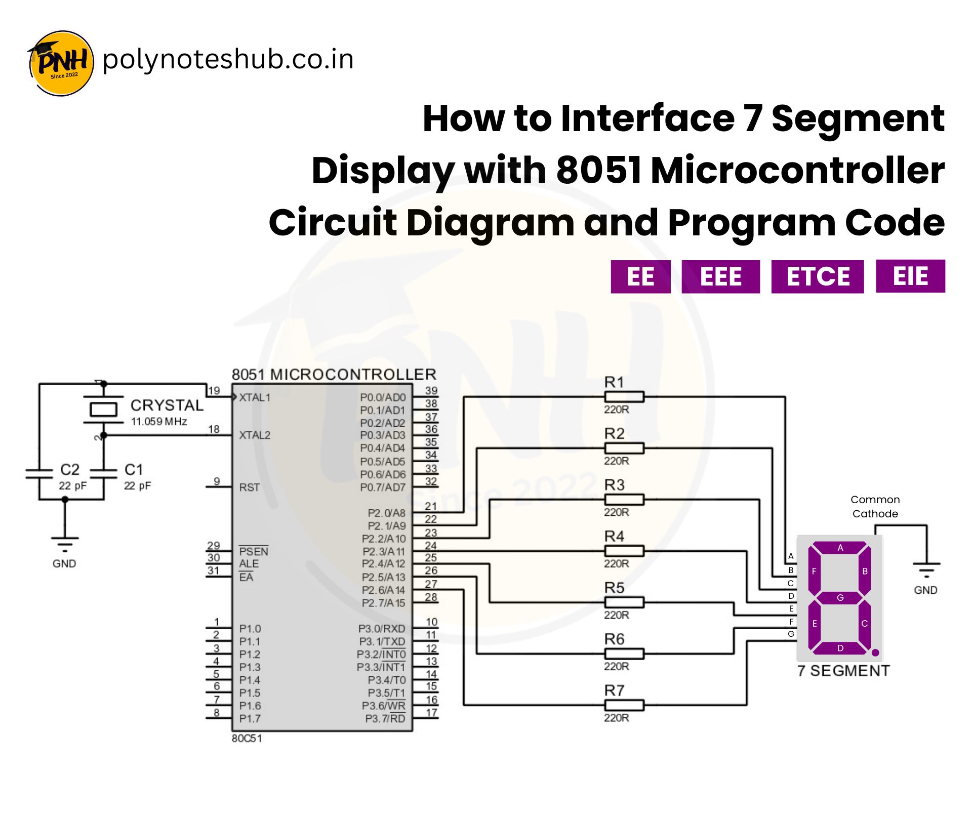
Circuit Diagram of Interfacing 7 Segment Display with 8051 Microcontroller

Connection Details of Interfacing 7 Segment with 8051 Microcontroller
- Connect the common cathode (CC) pin of the 7 segment display to GND of the microcontroller.
- Connect the A, B, C, D, E, F, G, and DP pins of the 7-segment display to P2.0, P2.1, P2.2, P2.3, P2.4, P2.5, P2.6, and P2.7 of the 8051 microcontroller.
- Use 220Ω resistors in series with each segment pin to limit the current.
- Connect the 8051 microcontroller to a power supply and the crystal oscillator circuit for proper functioning.
- Use a reset circuit with a push button and a pull-up resistor connected to the RESET pin of the microcontroller.
7 Segment Display Interfacing with 8051 in Assembly
Here is the 7 segment display interfacing with 8051 in assembly language –
ORG 0000H    ; Start from address 0
MOV P2, #0FFH ; Initialize Port 2 as output (all segments off)

MOV DPTR, #TABLE ; Load the address of the lookup table
MAIN:
    MOV R0, #0    ; Initialize loop counter (R0)
LOOP:
    MOV A, R0      ; Load the counter value into accumulator
    MOVC A, @A+DPTR ; Fetch the corresponding 7-segment code
    MOV P2, A      ; Output the 7-segment code to Port 2
    ACALL DELAY    ; Call delay routine
    INC R0         ; Increment the counter
    CJNE R0, #10, LOOP ; Check if the counter reaches 10
    SJMP MAIN      ; Restart the loop
TABLE: DB 0C0H, 0F9H, 0A4H, 0B0H, 099H, 092H, 082H, 0F8H, 080H, 090H
        ; 7-segment codes for digits 0-9

DELAY: MOV R1, #250 ; Outer loop count
DELAY1: MOV R2, #250 ; Inner loop count
DELAY2: DJNZ R2, DELAY2
        DJNZ R1, DELAY1
        RET

END
7 Segment Display Interfacing with 8051 in C Program
Here is the 7 segment display interfacing with 8051 program in c program –
#include <reg51.h>

// Define the 7-segment codes for digits 0-9
unsigned char code digits[] = {0xC0, 0xF9, 0xA4, 0xB0, 0x99, 0x92, 0x82, 0xF8, 0x80, 0x90};

void delay(unsigned int time) {
    unsigned int i, j;
    for (i = 0; i < time; i++)
        for (j = 0; j < 1275; j++);
}

void main() {
    unsigned char i;
    while (1) {
        for (i = 0; i < 10; i++) {
            P2 = digits[i]; // Send the digit code to port P2
            delay(500);     // Wait for 500ms
        }
    }
}

