In this note, we are going to know about LCD Interfacing with 8051 Microcontroller. Welcome to Poly Notes Hub, a leading destination for Engineering Notes for Diploma and Degree Engineering Students.
Author Name: Arun Paul.
LCD Interfacing with 8051 Microcontroller
Interfacing an LCD with an 8051 microcontroller is a common task in embedded systems to display text or data. The 16×2 LCD is the most widely used display module for such projects, and it provides a simple way to interact with users.
Components Required for LCD Interfacing with 8051 Microcontroller
These are the components that are required to make this circuit –
- 8051 Microcontroller (e.g., AT89C51)
- 16×2 LCD module
- Resistors (for pull-ups if required)
- 10kOhm Potentiometer (for contrast adjustment)
- Connecting wires
- Power supply
- 11.059 MHz Crustal Oscillator ( One Piece )
- 22 pF two Capacitor
Pin Description of 16×2 LCD Module

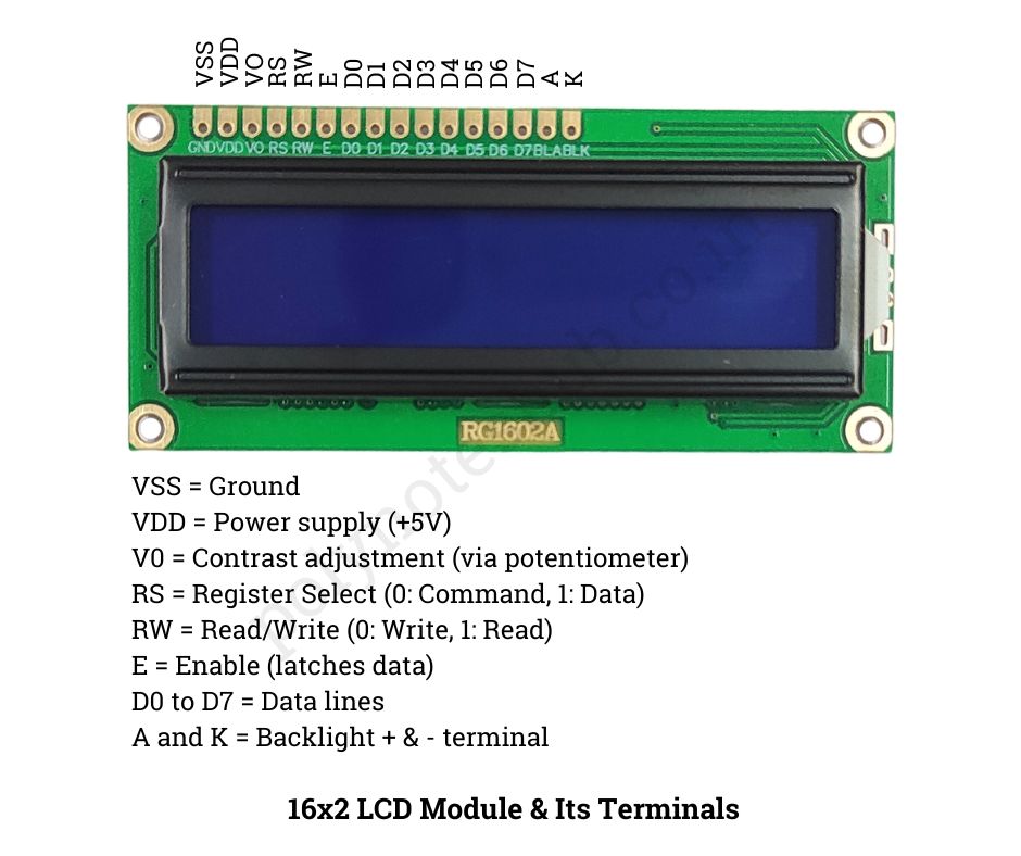
Here are the pin description of 16×2 LCD Module that is used in this circuit. Before using this display you have to know about each and every pin and their function of this display.
| Pin No | Name | Function |
|---|---|---|
| 1 | VSS | Ground |
| 2 | VCC | Power supply (+5V) |
| 3 | VEE | Contrast adjustment (via potentiometer) |
| 4 | RS | Register Select (0: Command, 1: Data) |
| 5 | RW | Read/Write (0: Write, 1: Read) |
| 6 | E | Enable (latches data) |
| 7 to 14 | D0 to D7 | Data lines |
| 15 | LED+ | Backlight positive terminal |
| 16 | LED- | Backlight negative terminal |
Before going to the circuit diagram, learn these topics to understand better.
📌 About 16×2 or 20×4 LCD Module. Both have same no of pins, names, and function.
📌 8051 Microcontroller and Its Pin Details. You have to get an idea about the pins of the 8051 Microcontroller.
Circuit Diagram of LCD Interfacing with 8051 Microcontroller

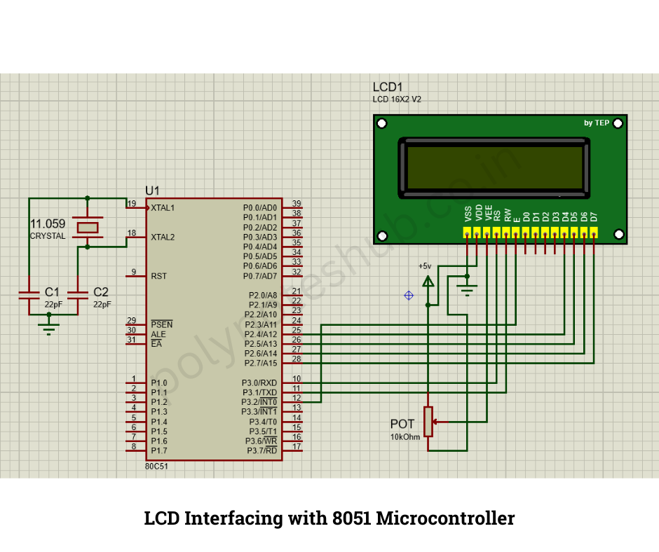
Above we shows the circuit connection of LCD Interfacing with 8051 Microcontroller –
- Power Connections: Connect VSS to GND and VCC or VDD to +5V power supply.
- Contrast Control: Connect a 10kOhm potentiometer between VCC and GND, with the wiper connected to VEE terminal of LCD Module.
- Data Lines: Connect the D4 to D7 lines to P2.4 to P2.7 of the 8051 microcontroller (We are using 4 bit mode).
- Control Lines:
- RS to P3.0
- RW to P3.1
- E to P3.2
- Backlight: Connect LED+ to VCC via a resistor and LED- to GND. ( This is note available in the circuit diagram )
- Crystal and Capacitor: A 11.059 MHz in between pin 18 and pin 19 with two 22 pF Capacitors.
Steps for Interfacing of LCD Interfacing with 8051 Microcontroller
- Initialization:
- Set the LCD in 4-bit mode or 8-bit mode as required.
- Configure display settings (cursor, blink).
- Sending Commands:
- RS = 0, RW = 0, send command on the data lines.
- Pulse E to latch the command.
- Sending Data:
- RS = 1, RW = 0, send data on the data lines.
- Pulse E to latch the data.
- Delay: Add appropriate delays between commands and data writes for the LCD to process.
LCD Initialization Commands
| Command | Function | Hex Code |
|---|---|---|
| Clear Display | Clears the screen and returns the cursor to the home position | 0x01 |
| Return Home | Returns cursor to the home position | 0x02 |
| Entry Mode Set | Moves cursor right and shifts display | 0x06 |
| Display ON, Cursor OFF | Turns on display, hides cursor | 0x0C |
| Display ON, Cursor ON | Turns on display and cursor | 0x0E |
| Function Set (4-bit mode) | Sets 4-bit mode, 2-line display | 0x28 |
Sample Code in C
This is the code for LCD Interfacing with 8051 Microcontroller –
#include <reg51.h>
sbit RS = P3^0;
sbit RW = P3^1;
sbit EN = P3^2;

// Function prototypes
void delay(unsigned int time);
void lcd_command(unsigned char cmd);
void lcd_data(unsigned char data);
void lcd_init();
void lcd_display(char *str);

void main() {
    lcd_init(); // Initialize the LCD
    lcd_display("Hello, World!"); // Display message
    while (1); // Infinite loop
}

void lcd_init() {
    lcd_command(0x28); // 4-bit mode, 2-line, 5x8 dots
    lcd_command(0x0C); // Display ON, Cursor OFF
    lcd_command(0x06); // Entry mode set
    lcd_command(0x01); // Clear display
    delay(5);
}

void lcd_command(unsigned char cmd) {
    P2 = (cmd & 0xF0); // Send upper nibble
    RS = 0; RW = 0; EN = 1; delay(1); EN = 0;
    P2 = ((cmd << 4) & 0xF0); // Send lower nibble
    EN = 1; delay(1); EN = 0;
    delay(2);
}

void lcd_data(unsigned char data) {
    P2 = (data & 0xF0); // Send upper nibble
    RS = 1; RW = 0; EN = 1; delay(1); EN = 0;
    P2 = ((data << 4) & 0xF0); // Send lower nibble
    EN = 1; delay(1); EN = 0;
    delay(2);
}

void lcd_display(char *str) {
    while (*str) {
        lcd_data(*str++);
    }
}

void delay(unsigned int time) {
    unsigned int i, j;
    for (i = 0; i < time; i++)
        for (j = 0; j < 1275; j++);
}
Applications
Here are some applications of LCD Interfacing with 8051 Microcontroller –
- Used in Real time data display in embedded systems.
- Used for Monitoring and diagnostics in industrial systems.
- Used for User interfaces for projects like calculators, clocks, and more.


