In this note, we are going to learn about LCD Interfacing with Arduino. Welcome to Poly Notes Hub, a leading destination for engineering notes for diploma and degree engineering students.
Author Name: Arun Paul.
What is Arduino UNO?
The Arduino Uno is a very popular development board in the Arduino community. It has an ATmega328P microcontroller, which serves as the board’s brain, as well as several input/output pins for connecting sensors, actuators, and other electronic components. The Uno also has a USB interface for programming and a power supply, making it simple to connect to a computer and upload code or power the board.
The Arduino Uno is noted for its simplicity and adaptability, making it suitable for both novices and expert users. It is often used for prototyping projects, experimenting with electronics, and developing interactive devices. With a big community and abundant documentation, the Arduino Uno is a popular choice among makers, students, and professionals working on a variety of projects.
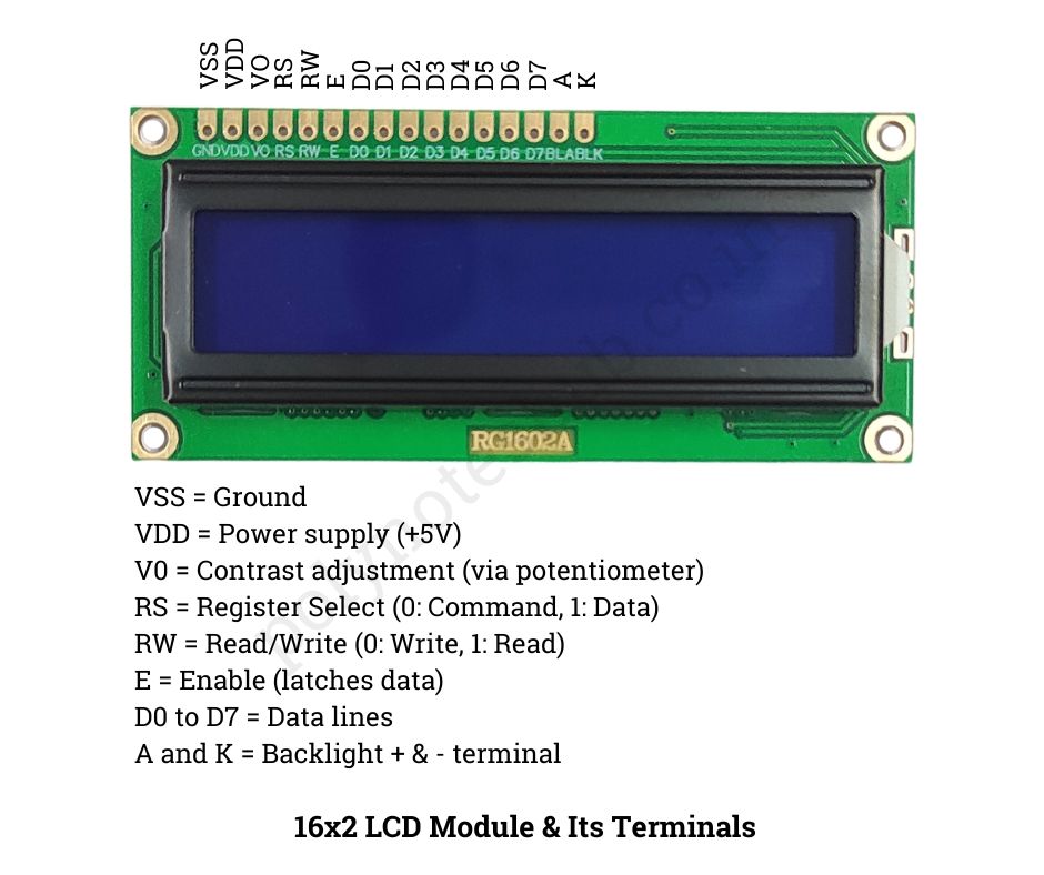
Pin Description of 16×2 LCD Module

Here are the pin description of 16×2 LCD Module that is used in this circuit. Before using this display you have to know about each and every pin and their function of this display.
| Pin No | Name | Function |
|---|---|---|
| 1 | VSS | Ground |
| 2 | VCC | Power supply (+5V) |
| 3 | VEE | Contrast adjustment (via potentiometer) |
| 4 | RS | Register Select (0: Command, 1: Data) |
| 5 | RW | Read/Write (0: Write, 1: Read) |
| 6 | E | Enable (latches data) |
| 7 to 14 | D0 to D7 | Data lines |
| 15 | LED+ | Backlight positive terminal |
| 16 | LED- | Backlight negative terminal |
Components Required for LCD Interfacing with Arduino
These are some components that are required to make this circuit called “LCD Interfacing with Arduino” –
- Arduino board (e.g., Uno, Mega, Nano)
- 16×2 LCD screen
- 10kΩ potentiometer (Used for contrast adjustment)
- Resistor (220Ω for backlight LED)
- Jumper wires
- Breadboard
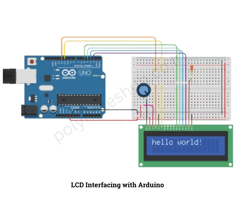
Pin Connections for LCD Interfacing with Arduino

This is the pin connections of this circuit diagram –
- RS to Arduino Pin 12
- E to Arduino Pin 11
- D4 to Arduino Pin 5
- D5 to Arduino Pin 4
- D6 to Arduino Pin 3
- D7 to Arduino Pin 2
- VSS to Ground
- VDD to +5V
- VO to Middle pin of potentiometer
- RW to Ground
- LED+ to 5V (via 220Ω resistor)
- LED- to Ground
Code of LCD Interfacing with Arduino
Here is the code for LCD Interfacing with Arduino UNO or with any types of Arduino Module –
#include <LiquidCrystal.h>

int seconds = 0;
LiquidCrystal lcd_1(12, 11, 5, 4, 3, 2);

void setup()
{
  lcd_1.begin(16, 2); // Set up the number of columns and rows on the LCD.
}

void loop()
{
  // set the cursor to column 0, line 1
  // (note: line 1 is the second row, since counting
  // begins with 0):
  lcd_1.setCursor(0, 0);
   // Print a message to the LCD.
  lcd_1.print("hello world!");
}
