Introduction
The Silicon Controlled Rectifier (SCR) is a four-layer semiconductor device belonging to the family of thyristors, widely utilized in numerous electronic and power control applications. With its remarkable capability to handle high currents and voltages, the SCR has become an indispensable component in modern electronics and electrical systems. The device operates on a unique principle of gate control, where a small current applied to the gate terminal can trigger the conduction of a much larger current from the anode to the cathode. This feature makes SCRs highly versatile and efficient in various industrial and consumer applications.
What is SCR?
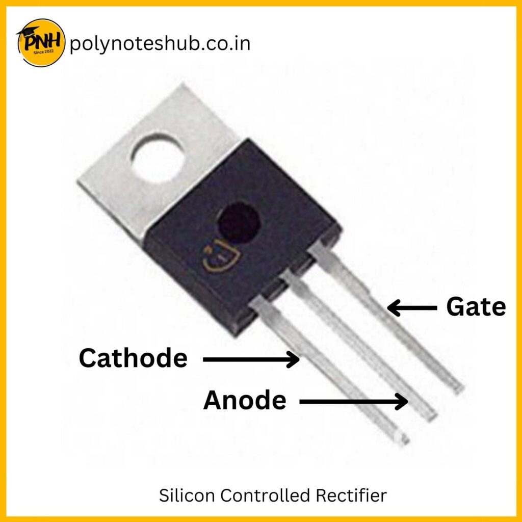
SCR stands for Silicon Controlled Rectifier. It is a four-layer semiconductor device that belongs to the family of thyristors. SCR is widely used in various electronic and power control applications due to its ability to handle high currents and voltages.

Construction of SCR

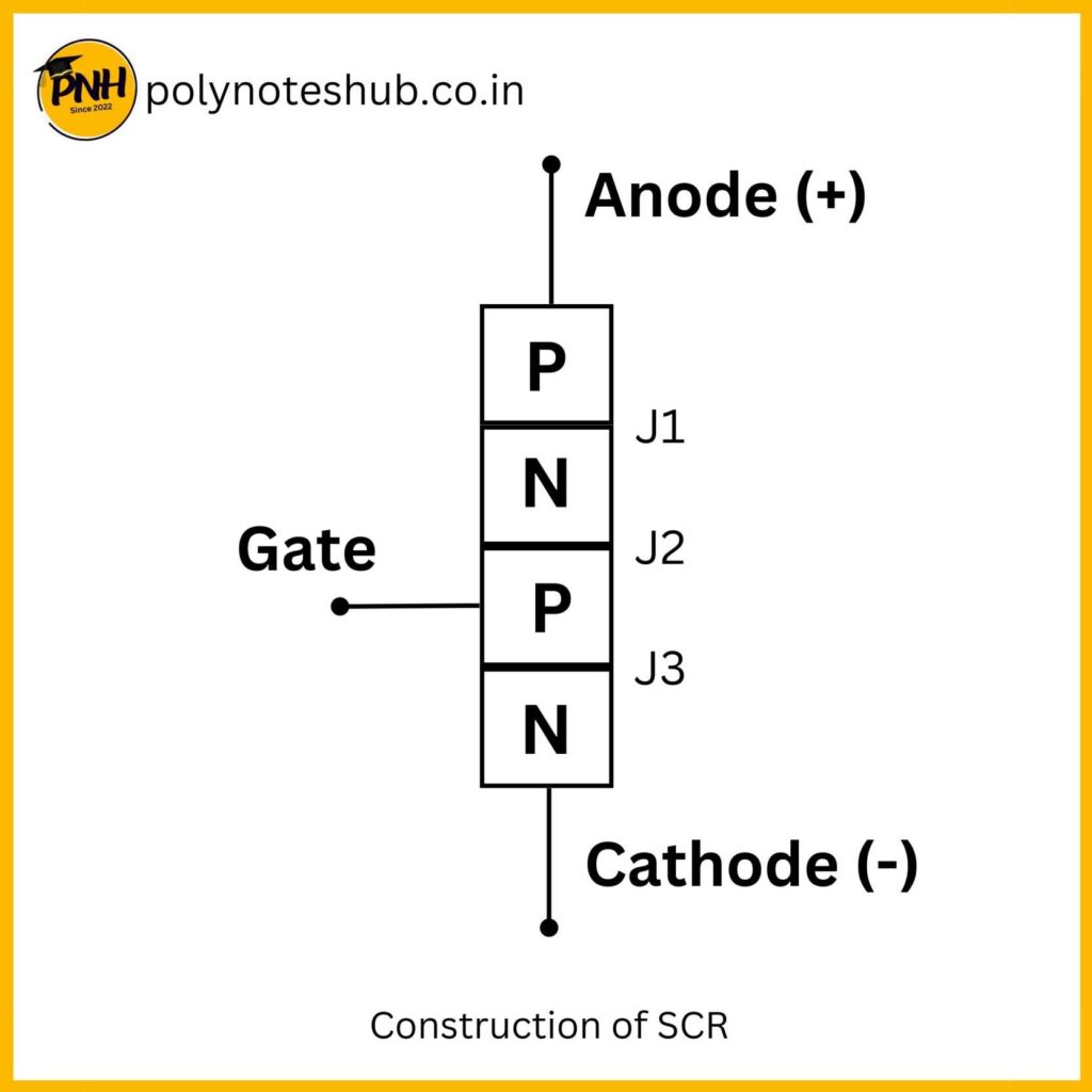
An SCR has three main terminals: Anode, Cathode, and Gate, and also three junctions called J1, J2, and J3.
- Anode: The anode is the positive terminal of the SCR through which the current enters the device.
- Cathode: The cathode is the negative terminal of the SCR through which the current exits the device.
- Gate: The gate is the control terminal that regulates the flow of current between the anode and the cathode.
The SCR also has a fourth layer called the “gate-cathode n-p-n” junction, which allows the control of current flow through the device.
Working principle of SCR
The basic working principle of an SCR involves the control of current flow from the anode to the cathode by applying a small current to the gate terminal.
The device remains in the OFF state (high impedance) until a positive voltage pulse is applied to the gate terminal. Once the gate current exceeds a certain threshold value, the SCR turns ON and allows current to flow through it. Once turned ON, the device remains conducting even if the gate current is removed.
To turn OFF the SCR, the anode current must be reduced to below a specified value, called the holding current, or the power supply must be interrupted.
V-I Characteristics of SCR
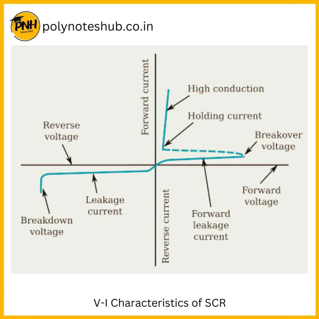
The VI (Voltage-Current) characteristics of a Silicon Controlled Rectifier (SCR) depict the relationship between the voltage applied across its terminals and the resulting current flowing through it. The characteristics of an SCR can be divided into two main regions: Forward Characteristics and Reverse Characteristics.

1. Forward Characteristics: In the forward characteristics of an SCR, the anode is kept positive with respect to the cathode, and a positive gate current is applied to trigger conduction. The graph shows the anode current on the y-axis and the anode-cathode voltage on the x-axis.
- Forward Breakover Voltage: This is the minimum voltage required across the anode-cathode junction to initiate forward conduction when the gate current exceeds the gate trigger current. It marks the point where the SCR switches from the OFF state to the ON state.
- Forward Voltage Drop: Once the SCR is in the ON state, it exhibits a low forward voltage drop between the anode and the cathode. This voltage drop, often called the “forward voltage,” is the voltage across the SCR when it is conducting.
2. Reverse Characteristics: In the reverse characteristics of an SCR, the anode is made negative with respect to the cathode. In this region, the SCR is in its OFF state, and the graph shows the reverse leakage current on the y-axis and the reverse voltage on the x-axis.
- Reverse Breakdown Voltage: This is the voltage at which the SCR experiences breakdown in the reverse direction, causing a sudden increase in reverse leakage current. It is essential to operate the SCR below its reverse breakdown voltage to prevent damage to the device.
Important Parameters:
- Gate Trigger Current: The minimum current required at the gate terminal to trigger the SCR into the ON state during forward conduction.
- Holding Current: The minimum current required to maintain the SCR in the ON state once it has been triggered. If the anode current falls below this value, the SCR turns OFF.
- Latching Current: It refers to the minimum current needed to sustain the ON state after triggering, keeping the device conducting even when the gate trigger current is removed.
Application of SCR
- Power control (motor speed, lamp dimming, AC regulation).
- Rectification (AC to DC conversion).
- Voltage regulation (stabilizers).
- Overcurrent protection.
- Soft starters.
- Power inverters.
Conclusion
In conclusion, the Silicon Controlled Rectifier (SCR) stands as a fundamental semiconductor device that revolutionized power control and regulation in modern electronics. Its ability to handle high currents and voltages while offering precise gate control has made it an invaluable component in various industrial and consumer applications. From power regulation, rectification, and voltage control to overcurrent protection and soft starters, SCRs have found their way into numerous electronic systems, contributing to their efficiency, reliability, and safety.
Read More

