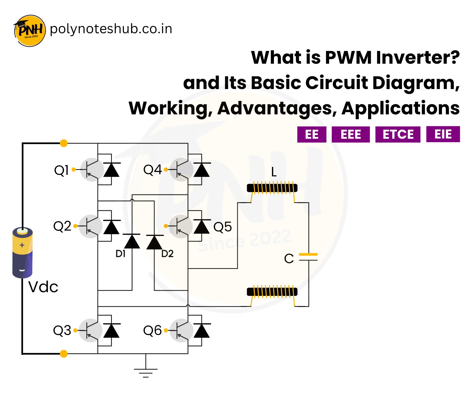
In this note, we are going to know about a topic called “What is PWM Inverter?” and PWM Inverter Circuit Diagram. Also about its types, advantages, and applications etc. Welcome to Poly Notes Hub, a leading destination for engineering notes for diploma and degree engineering students.
Author Name: Arun Paul.
What is PWM Inverter?
A PWM (Pulse Width Modulation) inverter uses pulse width modulation techniques to convert direct current (DC) to alternating current (AC). Unlike typical inverters, PWM inverters adjust voltage and frequency by regulating the width of the output waveform’s pulses. This results in a smoother AC output, lower harmonics, and higher efficiency.
PWM inverters are commonly employed in applications that need precise and efficient AC output, such as motor drives, renewable energy systems, and UPS systems.
Specifications of PWM Inverter
| Aspects | Value |
|---|---|
| Input Voltage | Typically 12V, 24V, or higher DC. |
| Output Voltage | Standard AC voltage (110V/220V AC depending on region). |
| Output Frequency | 50 Hz or 60 Hz. |
| Efficiency | Ranges from 85% to 98%, depending on the design. |
| Waveform Output | Sinusoidal (approximated or pure sine wave) |
| Switching Frequency | Generally ranges from 2 kHz to 20 kHz. |
| Harmonic Distortion | Low Total Harmonic Distortion (THD), typically below 5%. |
| Load Capacity | From a few watts to several kilowatts. |
Types of PWM Inverters
There are four types of Pulse Width Inverter Inverter, which are –
- Single Phase PWM Type Inverter
- Multiple Phase PWM Type Inverter
- Sinusoidal Phase PWM Type Inverter
- Phase Displacement PWM Type Inverter
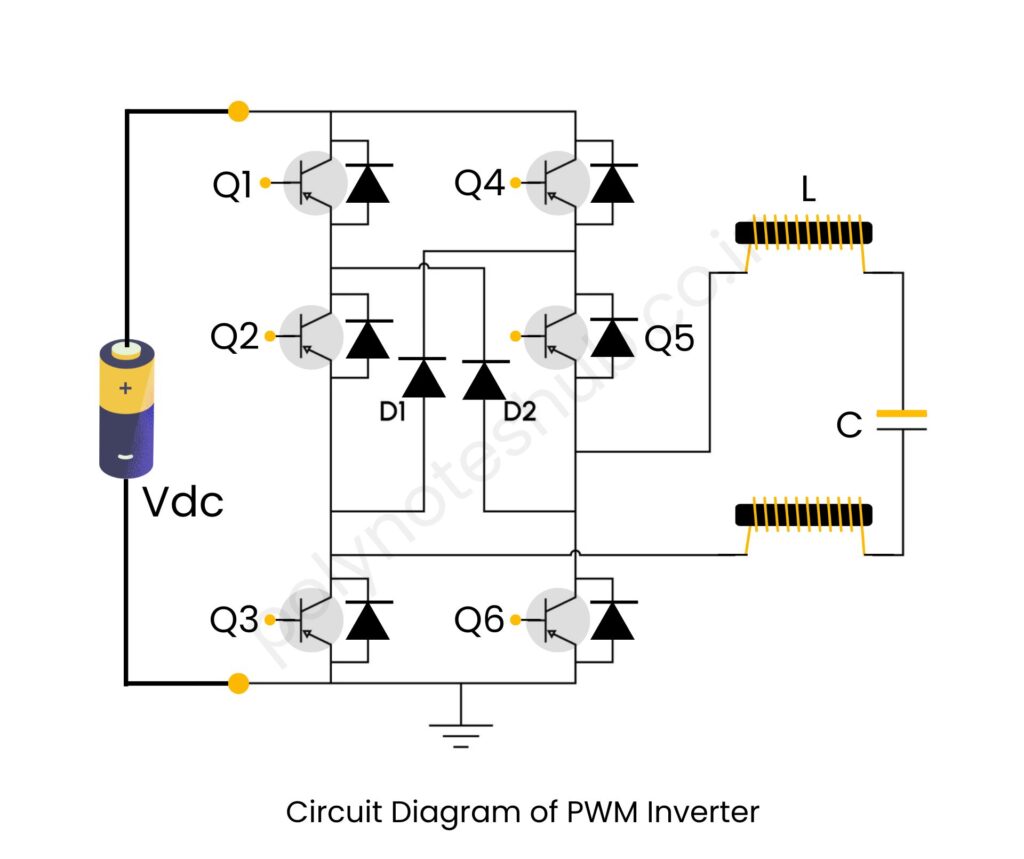
PWM Inverter Circuit Diagram

PWM Inverter Working Principle
The working idea of a PWM inverter is to generate a modulated AC signal from a DC source using pulse width modulation techniques. In a PWM inverter, a microcontroller or PWM generator generates a succession of high-frequency pulses of various sizes to simulate an alternating current waveform. These pulses are used to regulate the switching devices in an H-bridge circuit, which include MOSFETs and IGBTs. The H-bridge alters the polarity of the pulses, resulting in a raw alternating waveform.
The width of each pulse is modified based on the intended sinusoidal reference waveform, ensuring that the pulses’ average voltage corresponds to the shape of a sine wave. Because the H-bridge switches operate at high frequencies, the output is a series of chopped pulses with various widths that reflect the AC waveform. This high-speed switching mechanism minimizes power losses and increases efficiency.
The raw output of the H-bridge includes harmonics and is not a clean sine wave. To smooth the waveform and reduce harmonic distortion, the output is routed through an LC filter that includes an inductor and a capacitor. This filter removes the high-frequency components, leaving a near-sinusoidal AC waveform at the output. The filtered AC waveform is then delivered to the associated load, such as a motor or domestic appliance, to provide consistent and efficient power.
Output Voltage Equation of PWM Inverter
The output voltage equation is given by –

Where;
- Vdc = Input DC Voltage
- M = Modulation Index (0 ≤M ≤10).
- ω = Angular frequency (ω=2πf).
Output Current Equation of PWM Inverter
The output current equation is given by –

Where;
- Z = Impedance of the load
- Noted: The impedance depends on the Resistant, Inductive Reactance, and Capacitive Reactance.
Advantages of PWM Inverters
Here we have listed some advantages of this inverter –
- This type of inverters are improved efficiency by reducing energy losses.
- This inverter easily converts DC from solar panel.
- It has compact design using smaller components due to high switching frequencies.
- It allows for better regulation of output voltage and frequency.
- This type of inverter also suitable for renewable energy systems, improving overall energy utilization.
Applications of PWM Inverter
Here we have listed some applications of this inverter –
- It is provides precise control on motor speed.
- Used in Uninterruptible Power Supplies (UPS) for providing stable AC power when power is goes off.
- Used in electric vehicles to control motor and providing better efficiency.
- Used in HVAC systems to improve energy efficiency in heating, ventilation, and air conditioning.
- Also used for providing powers to the telecom engineering equipment and consumer electronics equipment.

