In this note, we are going to know about Parallel Inverter, and about its circuit diagram, working principle, advantages, disadvantages, and applications as well. Welcome to Poly Notes Hub, a leading destination for electrical engineering notes for diploma and degree engineering students.
Author Name: Arun Paul.
What is Parallel Inverter?
A parallel inverter is an inverter circuit in which the load is connected in parallel to the inverter’s output. It converts direct current (DC) to alternating current (AC), which is often utilized in high-power applications. Parallel inverters, as opposed to series inverters, are designed to manage greater loads more effectively by sharing the load among many inverter units.
📌 Specifications of Parallel Inverter
- Input Voltage: Varies depending on the design, typically 12V, 24V, or 48V DC.
- Output Voltage: Typically 110V or 220V AC (single-phase or three-phase).
- Output Power: Depends on the application, ranging from a few hundred watts to several kilowatts.
- Frequency: Usually 50Hz or 60Hz.
- Efficiency: Typically 85% to 95%.
- Waveform: Sine wave, modified sine wave, or square wave.
- Switching Devices: Generally uses transistors, thyristors, or MOSFETs.
- Protection: Includes overload, overvoltage, and short-circuit protection
Parallel Inverter Diagram
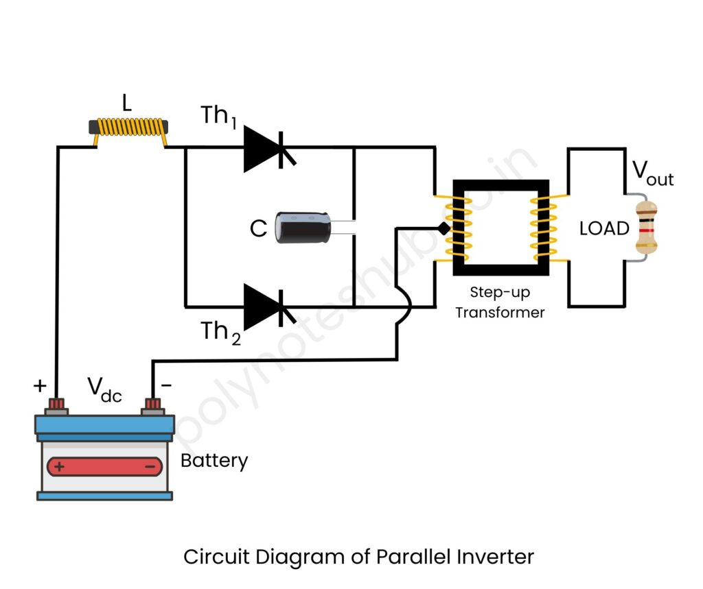
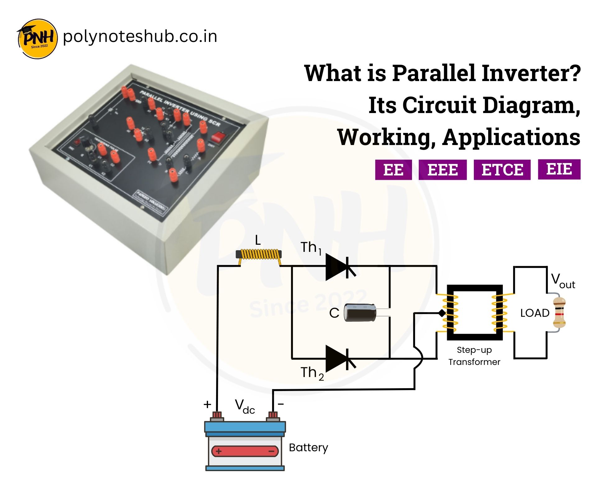
Here are the parallel inverter circuit diagram –

- A DC power supply.
- Two switching devices (like thyristors or transistors) connected in parallel.
- A step up transformer for voltage conversion.
- A commutating capacitor and inductor to maintain AC output.
- A load connected in parallel to the output
Parallel Inverter Working Principle
A parallel inverter converts DC power from a source to AC output via a sequence of synchronized steps. The inverter circuit is initially powered by a direct current source. To generate a pulsing DC waveform, switching devices such as transistors or thyristors alternate between on and off. The commutating components, which include a capacitor and an inductor, mold this waveform into a smooth AC signal. A step up transformer is used to increase the voltage to the desired AC output, assuring compliance with the connected load. Parallel inverters combine many units to efficiently distribute the load, minimizing stress on individual units and allowing the system to handle high-power applications.
A parallel inverter’s output voltage (Vout) is determined by its transformer and switching frequency. The equation below is widely used to examine the output –

where;
- VDC = Input DC Voltage
- Turns Ration = Ns / Np
- Ns = Number of turns in the secondary coil of the transformer.
- Np = Number of turns in the primary coil of the transformer.
and the frequency of the output waveform is given by –

where;
- T = Time period of one complete switching cycle.
Advantages of Parallel Inverter
Here we have listed some advantages of this circuit –
- The efficiency is high, so it can easily handle high load.
- It has load sharing capability that reduces the stress on individual inverter units.
- The modular design of this inverter allows for easy expansion.
- It is also suitable for industrial applications where high power is the first priority.
Disadvantages of Parallel Inverter
Here we have listed some disadvantages of this circuit –
- Increases the cost due to multiple units and complex circuitry.
- Maintenance charge is also high.
- This inverter also has the risk of circulating currents if units are not perfectly synchronized.
- This type of inverter requires precise synchronization of inverter units.
Parallel Inverter Applications
Here we have listed some applications of this circuit –
- It is used in uninterrupted power supplies (UPS) for high power loads.
- Used in drives for motors, pumps, and compressors.
- It is used to converts DC from solar panels or wind turbines to AC for grid-tied systems.
- This circuit or module powers AC motors from DC batteries.
- It provides backup power for communication towers in tele-communication engineering.
- It supplies power for heating, ventilation, and air conditioning.

