In this note, we are going to explain Foster Seeley Discriminator or Phase Discriminator Circuit Diagram, Working Principle, Phasor Diagram, Advantages, and Drawbacks. Welcome to Poly Notes Hub, a leading destination for polytechnic and degree engineering notes.
Author Name: Arun Paul.
What is Foster Seeley Discriminator or Phase Discriminator?
In FM (frequency modulation) receivers, a type of frequency demodulator circuit called the Foster-Seeley Discriminator, sometimes referred to as the Phase Discriminator, transforms frequency variations of the FM signal into corresponding amplitude (voltage) variations that represent the original modulating audio signal.
Applications of Foster Seeley Discriminator or Phase Discriminator –
- Used in FM receivers for demodulation.
- Used in communication systems to convert FM signals to audio.
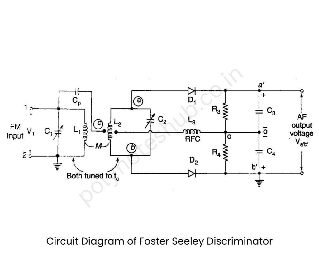
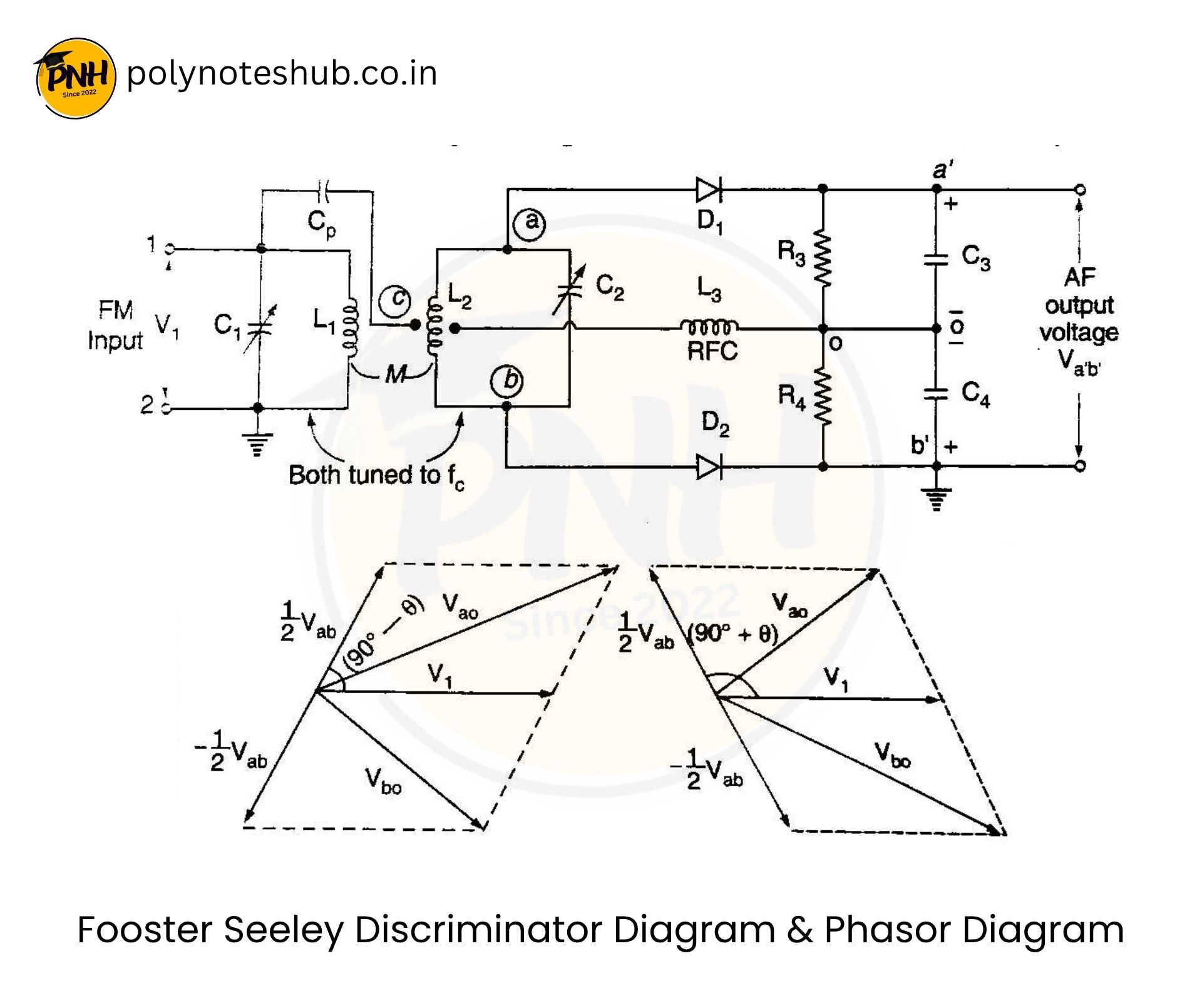
Foster Seeley Discriminator Circuit Diagram

If we compare this circuit with the balanced slope detector circuit, we will find that the diode and load arrangement are the same in both circuits. But the method of applying the input voltage to the diodes, which is proportional to the frequency deviation, is entirely different. The Foster Seeley discriminator is thus derived from the balanced modulator. However, here the primary and the secondary windings are both tuned to the same center frequency fₐ of the incoming signal. This simplifies the tuning process to a great extent, and it will yield better linearity than the balanced slope detector.
Explain Foster Seeley Discriminator Working Principle
Here we explain the principle of operation of foster seeley discriminator –
Even though the primary and secondary tuned circuits are tuned to the same center frequency the voltages applied to the two diodes D₁ and D₂ are not constant. They may vary depending on the frequency of the input signal. This is due to the change in phase shift between the primary and secondary windings depending on the input frequency.
The result of this is as follows :
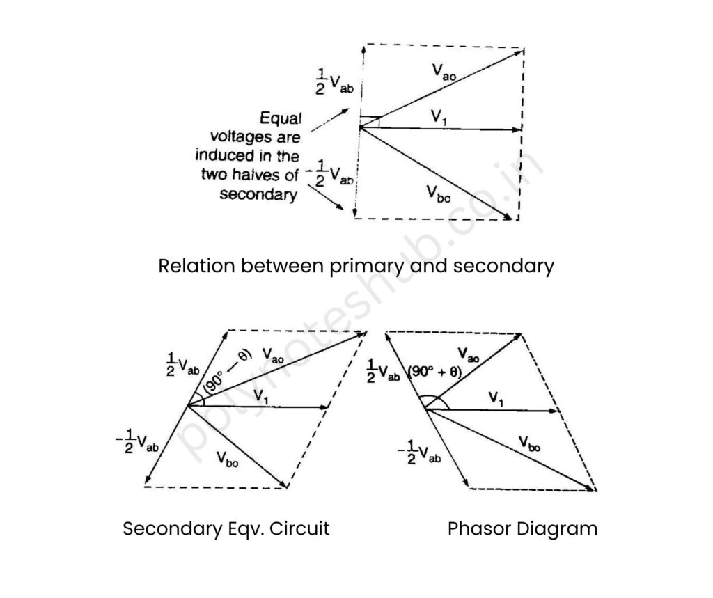
(i) At f₁ = fc, the individual output voltages of the two diodes will be equal and opposite. The output voltage is zero as,
V₀ = V₀₁ – V₀₂
(ii) For f₁ > fc, the phase shift between the primary and secondary windings is such that the output of D₁ is higher than D₂. Hence, the output voltage will be positive.
(iii) For f₁ < fc, the phase shift between the primary and secondary windings is such that output of D₂ is higher than that of D₁ making the output voltage negative.
This is clear if we observe the phasor diagrams of figure 4.43, 4.44(a) & 4.44(b). Because the output is dependent on the primary-secondary phase relationship, this circuit is called as phase discriminator.
Foster Seeley Discriminator Phasor Diagram
The phasor diagrams at different input frequencies are as shown in figure –

Advantages of Foster Seeley Discriminator
Here we have listed some advantages of the phase discriminator –
- Good linearity in output voltage vs. frequency characteristics.
- Simple design and reliable operation.
- Provides both frequency and amplitude discrimination, helping reject AM noise.
Disadvantages of Foster Seeley Discriminator
Here we have listed some drawbacks of the phase discriminator –
- Sensitive to amplitude variations (hence needs limiter circuit before it).
- Requires precise tuning for accurate performance.
- More complex than a ratio detector.

