Ratio Detector for FM Demodulation - Circuit Diagram, Working | New Topic
Diploma 1st Semester Notes Diploma 2nd Semester Notes Electrical Engineering Notes Electrical and Electronics Engineering Notes Electronics and Telecommunication Engineering Notes Electronics and Instrumentation Engineering Notes Diploma 1st Semester Notes Diploma 2nd Semester Notes Electrical Engineering Notes Electrical and Electronics Engineering Notes Electronics and Telecommunication Engineering Notes Electronics and Instrumentation Engineering Notes Diploma 1st Semester Notes Diploma 2nd Semester Notes Electrical Engineering Notes Electrical and Electronics Engineering Notes Electronics and Telecommunication Engineering Notes Electronics and Instrumentation Engineering Notes Diploma 1st Semester Notes Diploma 2nd Semester Notes Electrical Engineering Notes Electrical and Electronics Engineering Notes Electronics and Telecommunication Engineering Notes Electronics and Instrumentation Engineering Notes Diploma 1st Semester Notes Diploma 2nd Semester Notes Electrical Engineering Notes Electrical and Electronics Engineering Notes Electronics and Telecommunication Engineering Notes Electronics and Instrumentation Engineering Notes Diploma 1st Semester Notes Diploma 2nd Semester Notes Electrical Engineering Notes Electrical and Electronics Engineering Notes Electronics and Telecommunication Engineering Notes Electronics and Instrumentation Engineering Notes Diploma 1st Semester Notes Diploma 2nd Semester Notes Electrical Engineering Notes Electrical and Electronics Engineering Notes Electronics and Telecommunication Engineering Notes Electronics and Instrumentation Engineering Notes Diploma 1st Semester Notes Diploma 2nd Semester Notes Electrical Engineering Notes Electrical and Electronics Engineering Notes Electronics and Telecommunication Engineering Notes Electronics and Instrumentation Engineering Notes Diploma 1st Semester Notes Diploma 2nd Semester Notes Electrical Engineering Notes Electrical and Electronics Engineering Notes Electronics and Telecommunication Engineering Notes Electronics and Instrumentation Engineering Notes Diploma 1st Semester Notes Diploma 2nd Semester Notes Electrical Engineering Notes Electrical and Electronics Engineering Notes Electronics and Telecommunication Engineering Notes Electronics and Instrumentation Engineering Notes Diploma 1st Semester Notes Diploma 2nd Semester Notes Electrical Engineering Notes Electrical and Electronics Engineering Notes Electronics and Telecommunication Engineering Notes Electronics and Instrumentation Engineering Notes Diploma 1st Semester Notes Diploma 2nd Semester Notes Electrical Engineering Notes Electrical and Electronics Engineering Notes Electronics and Telecommunication Engineering Notes Electronics and Instrumentation Engineering Notes

Our Notes Categories


Ratio Detector for FM Demodulation – Circuit Diagram | New Topic

In this note, we are going to learn about the Ratio Detector for FM Demodulation and its circuit diagram. Welcome to Poly Notes Hub, a leading destination for engineering notes for polytechnic and degree engineering students.

Author Name: Arun Paul.

Ratio Detector for FM Demodulation

The Ratio Detector is a kind of FM (Frequency Modulation) demodulator that translates frequency variations in an FM signal to equivalent amplitude (voltage) variations that represent the original audio stream.

It is a modified Foster-Seeley discriminator that is less sensitive to amplitude changes (i.e., no amplitude limiter is required prior to demodulation).

Advantages of the Ratio Detector for FM Demodulation

  • There is no need for an amplitude limiter.
  • Better noise immunity than the Foster-Seeley discriminator or Phase Discriminator.
  • Stable output with less distortion.
  • Provides both DC and audio outputs, which are important for AGC (Automatic Gain Control).

Disadvantages of the Ratio Detector for FM Demodulation

  • The circuit complexity is slightly higher than Foster-Seeley.
  • To operate properly, the transformer circuit must be precisely aligned.

Circuit Diagram of Ratio Detector

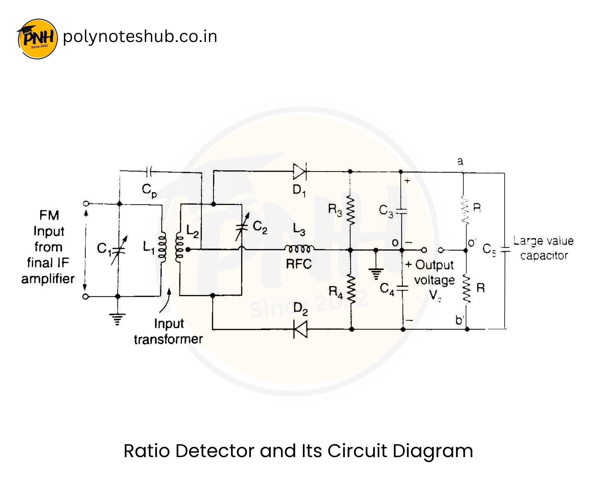
Here we have attached the ratio detector circuit diagram with circuit connection details –
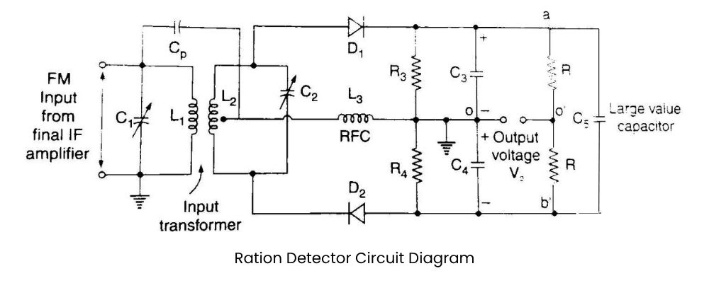
circuit diagram of ratio detector for fm demodulation - poly notes hub

Ratio detector is another frequency demodulator circuit. The circuit diagram of a basic ratio detector is shown in the figure.

If we compare this circuit with the Foster Seeley discriminator discussed in the previous section, we will find that these two circuits are identical except for the following changes:

See also  #2 - List of 5 Best Colleges in Siliguri in 2024 - Arts, Science, and Commerce

(i) The direction of diode D₂ is reversed.
(ii) A large value capacitor C₅ has been included in the circuit.
(iii) The output is taken somewhere else.

Operation or Working of Ratio Detector Circuit

It can be shown that the ratio detector output voltage is equal to half of the difference between the voltages developed across the two tuned circuits. Hence, the output voltage is proportional to the frequency deviation of the FM wave and therefore varies linearly with the modulating signal voltage. The phasor diagram of the ratio detector is identical to the phase discriminator. The type curve can be derived identically.

The ratio detector has an amplitude limiting action, which is incorporated due to the large value capacitor C5 in the circuit.

Amplitude Limiting by Ratio Detector

Let us discuss the reaction of the ratio detector circuit to the amplitude changes in the FM signal.

  1. If the amplitude of the FM input signal is applied at T1 input increases, the secondary voltage also increases. Due to this, the output voltage of the input transformer increases and the load voltage across R1, R2, and R3 will also increase.
  2. The increased load voltage across the load resistor increases the current flowing through diodes D1 and D2.
  3. The diode current flowing through capacitor C5 will start flowing. Hence, the load current increases.
  4. Since the voltage across the capacitor C5 will not change instantaneously, the voltage V1 is almost constant. Hence,
  5. The load voltage V2 has increased but the load voltage V1 has almost constant. Hence, the load voltage V1 – V2 will slightly decrease.
  6. The load has decreased because the increased load voltage increases the current flowing through the diodes. The Q decreases and therefore the gain of the input transformer is heavily damped.
  7. Due to heavy damping, the secondary voltage of the input transformer will decrease.
  8. This decrease in the amplitude of the FM input signal tries to decrease the load impedance Q.
  9. Changing amplitude compensates for the reduction in amplitude variations of FM signal.
See also  Electrodynamometer Instruments | Construction | Working | Merits | Demerits | New Topic [2023]

Hence, the ratio detector circuit provides the amplitude limiting by means of the process called Diode Variable Damping.

Share To:

Share This Post

Leave a Reply

Your email address will not be published. Required fields are marked *

Ratio Detector for FM Demodulation - Circuit Diagram, Working | New Topic

Our Notes Categories

Ratio Detector for FM Demodulation - Circuit Diagram, Working | New Topic

Our Notes Categories

Ratio Detector for FM Demodulation - Circuit Diagram, Working | New Topic

Our Notes Categories


Ratio Detector for FM Demodulation - Circuit Diagram, Working | New Topic
1st Year 1st SEM Notes ✭ 1st Year 2nd SEM Notes ✭ EE 2nd & 3rd Year Notes ✭ EEE 2nd & 3rd Year Notes ✭ ETCE 2nd & 3rd Year Notes ✭ EIE 2nd & 3rd Year Notes ✭ 1st Year 1st SEM Notes ✭ 1st Year 2nd SEM Notes ✭ EE 2nd & 3rd Year Notes ✭ EEE 2nd & 3rd Year Notes ✭ ETCE 2nd & 3rd Year Notes ✭ EIE 2nd & 3rd Year Notes ✭ 1st Year 1st SEM Notes ✭ 1st Year 2nd SEM Notes ✭ EE 2nd & 3rd Year Notes ✭ EEE 2nd & 3rd Year Notes ✭ ETCE 2nd & 3rd Year Notes ✭ EIE 2nd & 3rd Year Notes ✭ 1st Year 1st SEM Notes ✭ 1st Year 2nd SEM Notes ✭ EE 2nd & 3rd Year Notes ✭ EEE 2nd & 3rd Year Notes ✭ ETCE 2nd & 3rd Year Notes ✭ EIE 2nd & 3rd Year Notes ✭ 1st Year 1st SEM Notes ✭ 1st Year 2nd SEM Notes ✭ EE 2nd & 3rd Year Notes ✭ EEE 2nd & 3rd Year Notes ✭ ETCE 2nd & 3rd Year Notes ✭ EIE 2nd & 3rd Year Notes ✭ 1st Year 1st SEM Notes ✭ 1st Year 2nd SEM Notes ✭ EE 2nd & 3rd Year Notes ✭ EEE 2nd & 3rd Year Notes ✭ ETCE 2nd & 3rd Year Notes ✭ EIE 2nd & 3rd Year Notes ✭ 1st Year 1st SEM Notes ✭ 1st Year 2nd SEM Notes ✭ EE 2nd & 3rd Year Notes ✭ EEE 2nd & 3rd Year Notes ✭ ETCE 2nd & 3rd Year Notes ✭ EIE 2nd & 3rd Year Notes ✭ 1st Year 1st SEM Notes ✭ 1st Year 2nd SEM Notes ✭ EE 2nd & 3rd Year Notes ✭ EEE 2nd & 3rd Year Notes ✭ ETCE 2nd & 3rd Year Notes ✭ EIE 2nd & 3rd Year Notes ✭ 1st Year 1st SEM Notes ✭ 1st Year 2nd SEM Notes ✭ EE 2nd & 3rd Year Notes ✭ EEE 2nd & 3rd Year Notes ✭ ETCE 2nd & 3rd Year Notes ✭ EIE 2nd & 3rd Year Notes ✭ 1st Year 1st SEM Notes ✭ 1st Year 2nd SEM Notes ✭ EE 2nd & 3rd Year Notes ✭ EEE 2nd & 3rd Year Notes ✭ ETCE 2nd & 3rd Year Notes ✭ EIE 2nd & 3rd Year Notes ✭ 1st Year 1st SEM Notes ✭ 1st Year 2nd SEM Notes ✭ EE 2nd & 3rd Year Notes ✭ EEE 2nd & 3rd Year Notes ✭ ETCE 2nd & 3rd Year Notes ✭ EIE 2nd & 3rd Year Notes ✭ 1st Year 1st SEM Notes ✭ 1st Year 2nd SEM Notes ✭ EE 2nd & 3rd Year Notes ✭ EEE 2nd & 3rd Year Notes ✭ ETCE 2nd & 3rd Year Notes ✭ EIE 2nd & 3rd Year Notes ✭ 1st Year 1st SEM Notes ✭ 1st Year 2nd SEM Notes ✭ EE 2nd & 3rd Year Notes ✭ EEE 2nd & 3rd Year Notes ✭ ETCE 2nd & 3rd Year Notes ✭ EIE 2nd & 3rd Year Notes ✭ 1st Year 1st SEM Notes ✭ 1st Year 2nd SEM Notes ✭ EE 2nd & 3rd Year Notes ✭ EEE 2nd & 3rd Year Notes ✭ ETCE 2nd & 3rd Year Notes ✭ EIE 2nd & 3rd Year Notes ✭ 1st Year 1st SEM Notes ✭ 1st Year 2nd SEM Notes ✭ EE 2nd & 3rd Year Notes ✭ EEE 2nd & 3rd Year Notes ✭ ETCE 2nd & 3rd Year Notes ✭ EIE 2nd & 3rd Year Notes ✭ 1st Year 1st SEM Notes ✭ 1st Year 2nd SEM Notes ✭ EE 2nd & 3rd Year Notes ✭ EEE 2nd & 3rd Year Notes ✭ ETCE 2nd & 3rd Year Notes ✭ EIE 2nd & 3rd Year Notes ✭ 1st Year 1st SEM Notes ✭ 1st Year 2nd SEM Notes ✭ EE 2nd & 3rd Year Notes ✭ EEE 2nd & 3rd Year Notes ✭ ETCE 2nd & 3rd Year Notes ✭ EIE 2nd & 3rd Year Notes ✭ 1st Year 1st SEM Notes ✭ 1st Year 2nd SEM Notes ✭ EE 2nd & 3rd Year Notes ✭ EEE 2nd & 3rd Year Notes ✭ ETCE 2nd & 3rd Year Notes ✭ EIE 2nd & 3rd Year Notes ✭ 1st Year 1st SEM Notes ✭ 1st Year 2nd SEM Notes ✭ EE 2nd & 3rd Year Notes ✭ EEE 2nd & 3rd Year Notes ✭ ETCE 2nd & 3rd Year Notes ✭ EIE 2nd & 3rd Year Notes ✭ 1st Year 1st SEM Notes ✭ 1st Year 2nd SEM Notes ✭ EE 2nd & 3rd Year Notes ✭ EEE 2nd & 3rd Year Notes ✭ ETCE 2nd & 3rd Year Notes ✭ EIE 2nd & 3rd Year Notes ✭ 1st Year 1st SEM Notes ✭ 1st Year 2nd SEM Notes ✭ EE 2nd & 3rd Year Notes ✭ EEE 2nd & 3rd Year Notes ✭ ETCE 2nd & 3rd Year Notes ✭ EIE 2nd & 3rd Year Notes ✭ 1st Year 1st SEM Notes ✭ 1st Year 2nd SEM Notes ✭ EE 2nd & 3rd Year Notes ✭ EEE 2nd & 3rd Year Notes ✭ ETCE 2nd & 3rd Year Notes ✭ EIE 2nd & 3rd Year Notes ✭ 1st Year 1st SEM Notes ✭ 1st Year 2nd SEM Notes ✭ EE 2nd & 3rd Year Notes ✭ EEE 2nd & 3rd Year Notes ✭ ETCE 2nd & 3rd Year Notes ✭ EIE 2nd & 3rd Year Notes ✭ 1st Year 1st SEM Notes ✭ 1st Year 2nd SEM Notes ✭ EE 2nd & 3rd Year Notes ✭ EEE 2nd & 3rd Year Notes ✭ ETCE 2nd & 3rd Year Notes ✭ EIE 2nd & 3rd Year Notes ✭ 1st Year 1st SEM Notes ✭ 1st Year 2nd SEM Notes ✭ EE 2nd & 3rd Year Notes ✭ EEE 2nd & 3rd Year Notes ✭ ETCE 2nd & 3rd Year Notes ✭ EIE 2nd & 3rd Year Notes ✭ 1st Year 1st SEM Notes ✭ 1st Year 2nd SEM Notes ✭ EE 2nd & 3rd Year Notes ✭ EEE 2nd & 3rd Year Notes ✭ ETCE 2nd & 3rd Year Notes ✭ EIE 2nd & 3rd Year Notes ✭ 1st Year 1st SEM Notes ✭ 1st Year 2nd SEM Notes ✭ EE 2nd & 3rd Year Notes ✭ EEE 2nd & 3rd Year Notes ✭ ETCE 2nd & 3rd Year Notes ✭ EIE 2nd & 3rd Year Notes ✭ 1st Year 1st SEM Notes ✭ 1st Year 2nd SEM Notes ✭ EE 2nd & 3rd Year Notes ✭ EEE 2nd & 3rd Year Notes ✭ ETCE 2nd & 3rd Year Notes ✭ EIE 2nd & 3rd Year Notes

Our Notes Categories

Our Notes Categories